I am looking for a proven design 2 way diy active xover for use with my Nomex 164 and a sub which I will build using a Peerless 830668 and Lm3886 IC chipamp. I have googled and have found some schematics, but I do not want to waste time. As this will be my first active experience, I appeal to anyone that has actually built one from scratch. Tks in advance for the schematics.
Sorry fo rmy ignorance.. what are transfer curves. I do not have science /phusics background and do not understand certains terms.
For my first experience I am looking for a simple 2 to 4 stages opamp 2 way active filter .
I want to add a sub to my existing 2.5 peerless nomex 164 loudspeakers. Crossing over at 120-150 Hz .
For my first experience I am looking for a simple 2 to 4 stages opamp 2 way active filter .
I want to add a sub to my existing 2.5 peerless nomex 164 loudspeakers. Crossing over at 120-150 Hz .
You want an analogue active published design. (I think this should be clearer to those who know.)I am looking for a simple 2 to 4 stages opamp 2 way active filter .
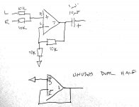
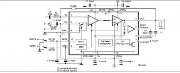
Tks Rabbitz. Interesting and fairly starightforward project from ESP. Nevertheless one question about summing of 2 LF output into one ( My LM3886 being mono). Is it ok to add 2 resistors paralelled as drawn the pic below resulting into a mono output? If so, what resistors values?
Attachments

"I want to add a sub to my existing 2.5 peerless nomex 164 loudspeakers. Crossing over at 120-150 Hz ."
then search in pass forum for my 'simple active crossover'
its a best sounding active crossover I made so far
based on high pass
low pass may need more filters after, I use plate amps
or go the my web page for opamp based
then search in pass forum for my 'simple active crossover'
its a best sounding active crossover I made so far
based on high pass
low pass may need more filters after, I use plate amps
or go the my web page for opamp based
Is it ok to add 2 resistors paralelled as drawn the pic below resulting into a mono output? If so, what resistors values?
The mixing resistors are 10K and are located at the input of the LP. So in between U1 output and the first R of the low pass you add a 10K for each channel so from there only 1 channel is required for the sub output. As you lose 6dB with the mixing resistors, you need a gain stage after them and before R and see a sketch of this stage and suggest 4K7 to ground instead of 10K to increase the gain. It also shows the details of the unused half of a dual op amp. If DC offset is high, then use a FET like the OPA2134 which I found helped in a pre amp that has stereo and mono outputs.
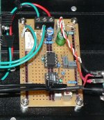
I've added a pic of my LP that goes to a LM3886. RCA in mono or stereo mixed (10k + 10K) > pot > gain > filter > norm (inverted)/rev > relay > out. One thing I had to add was a 100K to ground after R10 100R.
Attachments
Tks
 for all these details.I shall experiment the opamp based xover next week.
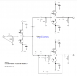
Adason : as regards the JFET version ,I have a bunch of Jtfets 2SK30. Do you thick they can be used in your project without making any modifications . I remenber building a simple guitar booster preamp and I had a difficult time adjusting voltages to get things ok (replacing J201 by 2SK30).
Adason : as regards the JFET version ,I have a bunch of Jtfets 2SK30. Do you thick they can be used in your project without making any modifications . I remenber building a simple guitar booster preamp and I had a difficult time adjusting voltages to get things ok (replacing J201 by 2SK30).
Thanks for pointing this to me. Please bear with me...I'm studied old classical subjects at school and my knowledge of electronics is basic...but few years ago, I became interested in basic electronics. I'm still a (bad) reader of schematics, a solderer of components and a kit builder. What are the complementary Jfets that you use in the posted schematics?
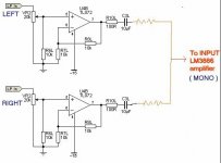
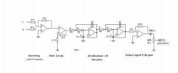
Thank you all for your suggestions. After heavy reading I have decided to go practical by breadboarding a simple LR from sound-au.com, progressively on to a 12 db and finally the 24 db/octave. The levels being too low for the TDA7293 DIY amp , I have tried several suggestions from different sources and applied to breadboard. Well the results became indeed interesting as progressively the bass came to life and my windows started shaking. I enclose the raw schematic so as to obtain inputs from all electronics specialists.
Please note that I have never followed any electronics courses but I have accumulated basic knowledge from reading a lot of reading of electronics materials. So please feel free to input your suggestions to improve the circuit.
Here are the several steps that I implemented ( they may be erroneous) .
1. I wanted to low pass both channels ( Are there any advantages ?? I have read that the L and R low end signal are both identical) . However for diy experience I use the summing principle to mix the L and R signals (inverted opamp).
2. As the signal was still too low , I included a gain of 5.6 db just after the summing up.
3. Then the signal is filtered through the 24 db/octave low pass filter ( approx 100 Hz cutoff)
4. Finally as the filtered signal being still too low, I have included a amplified inverted circuit with a gain of 5 db.
5. The output RC filters is calculated to reject subsonic Hzs since there were too much vibrations causing boomy bass.
Attachments
Last edited:
- Home
- Loudspeakers
- Multi-Way
- 1st time going active- what proven diy 2 way for sub design