Pass DIY Addict
Joined 2000
Paid Member
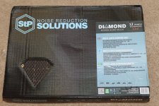
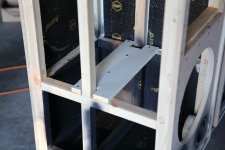
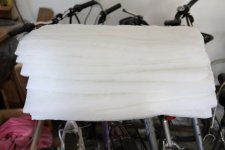
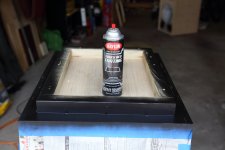
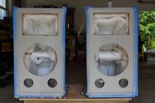
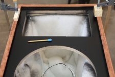
I added vibration damping material to the inside of the cabinets earlier today. I used the StandartPlast Bomb Aero that Tony recommended. I ordered 13 sheets but only used 12, so I have one left over for another project. The directions say to use a heat gun (which I have), but it was far easier and faster to just lay them out on the driveway in the sun. When they come out of the box, they are quite rigid and you can hold up the entire sheet from the edge. After baking in the sun for about 30 minutes, the sheets become quite soft and pliable. When they are soft, they cut relatively easily with a utility knife. They need to handled carefully after warming in the sun - holding them for more than a few seconds burns your fingers...
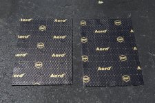
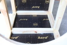
They are about 4mm thick, have a heavy foil top liner, a gooey-elastic middle layer, and an adhesive bottom layer. I warmed them up, cut pieces to size, peeled off the adhesive backing, and stuck them to the inside of the panels. Press firmly with a small piece of cloth to keep the heat off of your fingers. Then I used a staple gun to drive some 3/8" staples to help hold them in place.
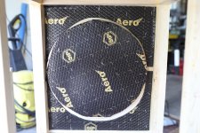
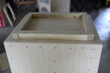
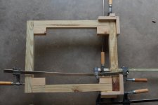
I also added an additional horizontal brace on top of the 2x2" brace that was already in place between the two sides. I made cutout for the 2x2 frame, added copious amounts of glue, and screwed the new piece down.
Things are starting to get heavy...
They are about 4mm thick, have a heavy foil top liner, a gooey-elastic middle layer, and an adhesive bottom layer. I warmed them up, cut pieces to size, peeled off the adhesive backing, and stuck them to the inside of the panels. Press firmly with a small piece of cloth to keep the heat off of your fingers. Then I used a staple gun to drive some 3/8" staples to help hold them in place.
I also added an additional horizontal brace on top of the 2x2" brace that was already in place between the two sides. I made cutout for the 2x2 frame, added copious amounts of glue, and screwed the new piece down.
Things are starting to get heavy...
Attachments
Last edited:
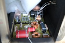
The woofer board is fine as to coil position. Same as tweeter board. Reason? Separation distance.
I wouldn't worry about it.
You can leave it as it is, or you can try to improve it without too much hassle.
Here's an example of inductor crosstalk: Open Source Monkey Box
Edit: the Calapamos photos on page 9 of this document show the xovers for the woofer and the tweeter mounted just next to each other. I'd recommend to keep them further apart from each other.
Last edited:
Pass DIY Addict
Joined 2000
Paid Member
This link is a resource that I've often referenced in the past: Placement of Coils in Crossover Network
I'll look and see if there is an easy way to re-orient that large foil cap in the woofer network. Not sure how easy this might be or if I actually want to do this. I have some confidence in Tony's engineering that he wouldn't have designed things in a way that creates problems.
I'll look and see if there is an easy way to re-orient that large foil cap in the woofer network. Not sure how easy this might be or if I actually want to do this. I have some confidence in Tony's engineering that he wouldn't have designed things in a way that creates problems.
Last edited:
Pass DIY Addict
Joined 2000
Paid Member
What part has been discontinued? Is Tony not making the crossovers anymore? I purchased mine from him in Dec 2020 or Jan 2021. Some of the coils were custom made by the respective manufacturers. The woofer seems to be out of stock just about everywhere. To my knowledge (inquired with Kevin at Faital Pro) it has not been discontinued, just out of stock with no quote on lead time. Maybe it’s a casualty of the global shipping woes, or maybe that is manufacturer code speak for End Of Life…
When I couldn’t find the woofer anywhere, I posted in the Swap Meet forum. Malcolm messaged me and offered a pair for me to purchase - This is such an awesome community!
When I couldn’t find the woofer anywhere, I posted in the Swap Meet forum. Malcolm messaged me and offered a pair for me to purchase - This is such an awesome community!
I'll look and see if there is an easy way to re-orient that large foil cap in the woofer network. Not sure how easy this might be or if I actually want to do this. I have some confidence in Tony's engineering that he wouldn't have designed things in a way that creates problems.
I wouldn't worry about the capacitor(s) at all. Just move some of the inductors off-board and mount them at a 90° angle and at a distance from the other inductors. Soldering them is actually a lot easier than you might think.
That said, it might be possible that Tony actually mounted the inductors as they are on purpose, implying that the crosstalk is actually part of the design. I'd consider this a bit awkward, but you never know. Just ask him for this thoughts.
Pass DIY Addict
Joined 2000
Paid Member
Pass DIY Addict
Joined 2000
Paid Member
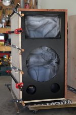
I decided to leave the crossovers alone and install them as is. It was a bit of a trick to find screws narrow and long enough to go through the mounting collars on the board. After the crossovers were mounted, I attached the last side panel to each cabinet and added the last of the vibration damping material to the new panel.
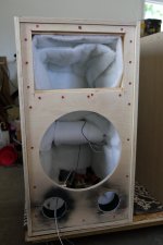
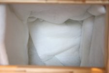
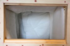
I ordered 10 yds of 30" wide 1.25" thick polyester batting to go into the cabinets. I cut strips to go all around the inside and stapled in two layers. In a few places, it ended up being 3-4 layers thick because of overlap, folding etc.
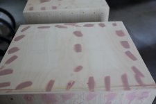
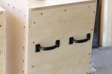
It seemed to get a strange case of the measles after the cabinet was closed... Finally for today, I added a set of heavy-duty handles to the back of each cabinet so I'd have some way to grab and lift it now that the cabinet is closed up.
I ordered 10 yds of 30" wide 1.25" thick polyester batting to go into the cabinets. I cut strips to go all around the inside and stapled in two layers. In a few places, it ended up being 3-4 layers thick because of overlap, folding etc.
It seemed to get a strange case of the measles after the cabinet was closed... Finally for today, I added a set of heavy-duty handles to the back of each cabinet so I'd have some way to grab and lift it now that the cabinet is closed up.
Attachments
Pass DIY Addict
Joined 2000
Paid Member
At this point, I'm waiting on veneer to arrive in the mail. The only things left now are filling screw holes with Bondo and finishing the stands.
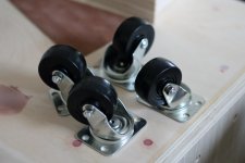
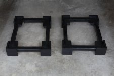
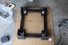
I've got one stand built and painted. The other one still needs a little bit of sanding before it gets some paint. I also added the footer to each speaker that will sit in the stand. This was a good opportunity to use up some small scraps of lumber that I've had laying around in the garage for a while now. The footer was glued and screwed to the bottom, then painted black with some truck bed coating. I was also figuring that maneuvering these into position might be a bit of a challenge, so I picked up some caster wheels that well be attached to the bottom of the stands. The wheels will stick out from the vertical wooden panels on the stand by about 1cm.
I've got one stand built and painted. The other one still needs a little bit of sanding before it gets some paint. I also added the footer to each speaker that will sit in the stand. This was a good opportunity to use up some small scraps of lumber that I've had laying around in the garage for a while now. The footer was glued and screwed to the bottom, then painted black with some truck bed coating. I was also figuring that maneuvering these into position might be a bit of a challenge, so I picked up some caster wheels that well be attached to the bottom of the stands. The wheels will stick out from the vertical wooden panels on the stand by about 1cm.
Attachments
Last edited:
Pass DIY Addict
Joined 2000
Paid Member
Thanks, Danny! That's a pretty nice looking design you built as well!
A question for anyone that has built something with a large drivers. I'm looking for a grille/guard for the 15" driver, but I'm unsure how to choose one. Fer of them provide adequate details about their specific diameters or how they mount in order for me to properly choose.
The Faital Pro 15PR400 driver has an outer diameter of 395mm. I'm looking for something to either sit on top of the driver gasket or span the entire woofer diameter and mount directly to the front baffle, straddling the driver.
Many of the round grilles that I've found on Amazon say they have a 380mm outside diameter. I presume the driver is intended to mount from behind the baffle and the grille is intended to mount on the front of the baffle. So, something of this size won't work in this situation.
Any ideas on how I can protect this driver?
Thanks !
I like the look of the Goldwood bar tube grills in chrome or black.
Do not use a grill that is very dense because it will alter the frequency response.
Those Goldwood tube grills don't have that problem")
I like the look of the Goldwood bar tube grills in chrome or black.
Do not use a grill that is very dense because it will alter the frequency response.
Those Goldwood tube grills don't have that problem
Pass DIY Addict
Joined 2000
Paid Member
Pass DIY Addict
Joined 2000
Paid Member
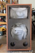
I finished adding the final coat of bed liner to the bases today. After the paint dried, I added a set of caster wheels to make it easier to get the speakers into position.
I also finished filling the nearly 350 screw holes and gave the front baffles a coat of primer. The front edges of the cabinet were taped off because glue sticks to raw wood much better than it does to painted wood. The 5mm strips of Bubinga hardwood will be glued to the front edges. Veneer is supposed to arrive tomorrow, the cabinets are almost ready...
I also finished filling the nearly 350 screw holes and gave the front baffles a coat of primer. The front edges of the cabinet were taped off because glue sticks to raw wood much better than it does to painted wood. The 5mm strips of Bubinga hardwood will be glued to the front edges. Veneer is supposed to arrive tomorrow, the cabinets are almost ready...
Attachments
Last edited:
Pass DIY Addict
Joined 2000
Paid Member
Pass DIY Addict
Joined 2000
Paid Member
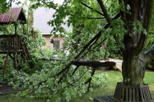
Got the tree all cleaned up, time to work on the speakers again!
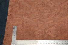
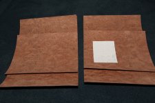
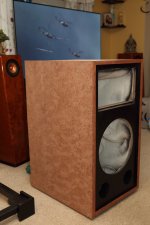
The baffles have been primed, sanded, and painted with flat black paint followed by 4 or 5 coats of matte finish clearcoat and a light sanding with 2000 grit wet/dry paper so they are super smooth. I prepped the veneer by cutting and numbering the pieces so I can veneer the left side, top, and right side of each cabinet without disrupting the pattern in the grain. I found cutting the veneer from the wood side to be easier than cutting through the paper backing first. I used my T-square and clamped each end to a strip of wood, sandwiching the veneer between the two, using the metal edge of the square as a guide for my razor knife. I started with a new blade and changed it half way through the job to make sure I was always getting a clean cut. It's no surprise, but cutting along the grain is waaaay easier than cutting across the grain. Make multiple passes, cut a little at a time, and it all goes pretty smoothly.
I glued my hardwood strips to the edge of the front baffle next. This was a tedious process of trial and error to get things to line up with nice 45 degree angles at the corners. I mounted the hardwood so the edge left an elevated lip on the top and sides of the cabinet. This way, I have a hard edge for placing the veneer. I'll trim the remaining overhang with my router or with sandpaper and a sanding block to make it flush with the face of the veneer. This will keep the edge of the veneer out of sight.
To prep for veneer, I brought the cabinet into the house and laid out the veneer pieces on the table overnight in the air conditioning so the surface humidity levels would be similar. Not sure that this really made a difference as spreading the glue on both surfaces made them both pretty wet again. Oh well. I used a 1" diameter sponge roller with a smooth surface to spread the glue on the cabinet and on the veneer. The cabinet got two coats of glue with enough time for it to dry pretty thoroughly between coats. The veneer received a single layer of glue. I went back and forth with the roller until the layer of glue was smooth and even. The resulting surface was an eggshell pattern in the reflected light. I was a little nervous afterward because the figured pattern on the veneer got a little wavy as it swelled from the moisture in the glue. I don't remember this happening with the quartersawn veneer that I used with my last project. This, too, sat until the glue was dry.
When both were thoroughly dry, I used a dry iron set to the "cotton" setting (one setting below the hottest setting of "linen") with a piece of kraft paper between the iron and the veneer to prevent any scorching and to make sure there was a smooth surface for running the iron back and forth.
I started in the middle of the edge that meets the hardwood around the front baffle and made sure it was firmly butted up against the wood so there were no gaps. With slow and steady pressure, I moved first to one end, then to the other, tacking down the entire edge of the veneer. Starting in the middle and moving out to each edge helps to prevent any bubbles from getting trapped under the veneer. Then, returning to the middle of the strip that was just ironed along the baffle, I moved toward the back of the cabinet a little and swept out toward both sides again. Working methodically and from the center to the outer edges, the veneer gets tacked town nice and smoothly. Go smoothly and slowly, allowing the veneer to heat evenly so the glue sets. Use firm pressure on the iron and keep it moving.
The final image is with just one side veneered. I need to get more glue at the store before I can do any more. The speaker in the background is my Frugal Horn XL from a few years ago. Though there is only 4cm difference in height and the bases are the same depth, the Calpamos looks WAAAY bigger than the FHXL because the FHXL has a curved and sculpted profile.
Attachments
Last edited:
Pass DIY Addict
Joined 2000
Paid Member
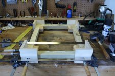
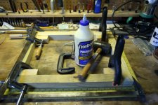
Yeah, it's an interesting construction technique that uses a frame of 2x2s as a skeleton. Everything else I have made just used a "standard" box configuration with butt-joints. Though it was a bit of a trick to actually get all square joints for the frame, it made it much easier to attach panels and get air-tight joints by using plenty of glue and screws. None of my clamps are longer than 3 feet, so using screws was an added bonus for ease of "clamping" panels while the glue dried.
I don't remember how I first came across Bubinga wood, but I really like the grain patterns and the way the colors shift along with the direction of the light. If you look from one end of the grain pattern with a light, there are darker areas and lighter areas. If you look from the opposite end of the grain pattern, the darker areas become lighter and the lighter areas become darker. It's a pretty cool effect.
I don't remember how I first came across Bubinga wood, but I really like the grain patterns and the way the colors shift along with the direction of the light. If you look from one end of the grain pattern with a light, there are darker areas and lighter areas. If you look from the opposite end of the grain pattern, the darker areas become lighter and the lighter areas become darker. It's a pretty cool effect.
- Home
- Loudspeakers
- Multi-Way
- My Calpamos Build