This is my FIRST-TIME experience with bass-reflex design. I, in fact, usually get used to closed box design. Also, this is my first-time using computer-aided design; a BassBox 6 Pro.
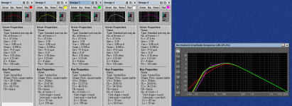
I've created 5 designs. I need a hand on help select choice which one is the best, in your opinions. The driver is JBL LC-S1250W. Parameter of the driver is shown in pics.
Design 1: Closed box, 85L, Q = 0.41 (Actually, in calculation, I intended to set it at 0.5, but the program said it is 0.41)
Design 2: Vented box, 78L, Vent diameter = 5.7 cm., Vent length = 17.8 cm.
Design 3: Vented box, 78L, Vent diameter = 6.5 cm., Vent length = 19.5 cm.
Design 4: Vented box, 78L, Vent diameter = 5.7 cm., Vent length = 6.49 cm.
Design 5: Vented box, 78L, Vent diameter = 6.5 cm., Vent length = 9.1 cm.
For the reason of Vb of vented boxes were 78L because I tried to use a Keele & Hoge alignment which said to be equal to Bessel alignment with Ql = 3, but I'm not sure if my understanding is correct.
I'd love to hear any comments and suggestions. Thank you in advance.
Attachments
Last edited:
The size could be good, but the port is to small, i would use a 78L with a 10cm diameter port of 24cm long, that for a tuning to 31Hz and a F3 of 30.9Hz.
This is based on specs i found here: Dôme acoustique : Paramètres haut-parleur de THIELE et SMALL, sans filtre ni ampli
and simmed fast in the freeware WinISD (WinISD - Linearteam)
This is based on specs i found here: Dôme acoustique : Paramètres haut-parleur de THIELE et SMALL, sans filtre ni ampli
and simmed fast in the freeware WinISD (WinISD - Linearteam)
Last edited:
According to my calculations, this driver in an unfilled closed box of 85.4 litres gives a Qtc of 0.5 with fc=41.3 Hz and f3c=64.2. So your calculation of 85 litres for Qtc of 0.5 is correct for an unfilled closed box.
Your programme specifies heavy filling, and this is, I think, where the discrepancy lies. A fill factor of 2.45 (*very* heavy filling) yields a Q of 0.4087 and -3dB at 69.4 Hz.
Personally I'm biased and generally prefer a closed box over a reflex enclosure. YMMV, of course.
Your programme specifies heavy filling, and this is, I think, where the discrepancy lies. A fill factor of 2.45 (*very* heavy filling) yields a Q of 0.4087 and -3dB at 69.4 Hz.
Personally I'm biased and generally prefer a closed box over a reflex enclosure. YMMV, of course.
Using Hornresp and assuming the math here is accurate for a Bessel alignment, then using Qes in lieu of Qts to account for some system losses: Dôme acoustique : Sélection de HP pour enceintes bass-reflex avec un alignement BESSEL
Vb = ~67.4 L, Fb = 23.14 Hz
A 'classic' BR = [measured] Vas/1.44 tuned to Fs.
The math I use for T/S, a max flat BR = ~82.1 L tuned to ~29.9 Hz
In each case even a 4"/10.16 cm dia. vent is a bit small [mid 20s ms/120 W], so may need some vent damping to 'taste'") .
.
Over the decades from before T/S I've used the 'classic' for BR, damping for fine tuning, so absent knowing anything about your intended app am inclined to ignore them all as is and for sure either figure out how to use WinISD for vent design or switch to Hornresp or other known accurate software.
Vb = ~67.4 L, Fb = 23.14 Hz
A 'classic' BR = [measured] Vas/1.44 tuned to Fs.
The math I use for T/S, a max flat BR = ~82.1 L tuned to ~29.9 Hz
In each case even a 4"/10.16 cm dia. vent is a bit small [mid 20s ms/120 W], so may need some vent damping to 'taste'
.Over the decades from before T/S I've used the 'classic' for BR, damping for fine tuning, so absent knowing anything about your intended app am inclined to ignore them all as is and for sure either figure out how to use WinISD for vent design or switch to Hornresp or other known accurate software.
None of the curves ook like anything i would consider.
What is the room situation?
dave
The room size is 5.52 x 2.62 x 7.62 m.
Update!
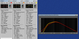
I've redesigned the system. This time, I reduced the cases to be only three.
Also, I've decided that I'd go for bass-reflex enclosure since I want to explore a new experience.
Design 1: conventional closed box (for reference), 85L, Q = 0.41
Design 2: vented box, 78L, vent diameter = 9.4 cm., vent length = 28.0 cm.
Design 3: vented box, 78L, vent diameter = 5.7 cm., vent length = 17.8 cm.
The design 2 was calculated following Vance Dickason's cookbook trying to use Bessel alignment with Ql = 3.
The design 3 cloned the vent dimension directly from B&W 801 Matrix S2. I saw it was tuned at the bottom of sonic spectrum; 19 Hz, thus, I was just interested in it. And the response simulated by the program wasn't bad in my view. But I'm not sure whether it will work well or have any problems, as the port was designed for specially use with its system.
I still need to hear comments from everyone. Please help to review my designs and help me to make a decision.
Attachments
What loss factor for the enclosure do you use? Quite high I’d say, for solid and not heavily damped reflex systems Q values between 10 and 20 are realistic.
I’m not sure whether you mean loss factor = Ql. If so, Ql is 3 in this case ( Design 2). In Dickason’s textbook, it is suggested that Ql should be in the range of 3 to 20. I chose Ql = 3 because I prefer larger box to smaller one. I was biased with closed box design that I’d prefer bigger volume.
Trick question... makes people focus on the rudimentary (and hypothetical) curves as if that was the starting and ending point of the exercise.
Although the #1 sealed box is rather too small, with a little broad boost at say 30-40 Hz, you have a good sounding sub which also has a nice FR. The sealed box will reduce distortion and will control the cone in the nether regions of the band so as to inhibit harmful flopping around from rumble noises on the recording. But that low resonance driver certainly deserves a bigger box, as fatmarley suggested.
With the other sims, all you get is a tuned box and a complex mix of sound from the cone and the port.
B.
Last edited:
That was what I meant.I’m not sure whether you mean loss factor = Ql. If so, Ql is 3 in this case ( Design 2). In Dickason’s textbook, it is suggested that Ql should be in the range of 3 to 20. I chose Ql = 3 because I prefer larger box to smaller one. I was biased with closed box design that I’d prefer bigger volume.
Ben has a point here. Although I think the modeling is quite reliable if done right. What people tend to forget is that TSP are small signal. Real life levels show another truth. I remember a friend who shortly worked at KEF late eighties saying: 'with the 104/2, KEF just created a lot of low output. Tailoring the response was done afterwards, with the K-ube.' So nothing new there. The Linkwitz Transform isn't something from yesterday either.Trick question... makes people focus on the rudimentary (and hypothetical) curves as if that was the starting and ending point of the exercise.
Although the #1 sealed box is rather too small, with a little broad boost at say 30-40 Hz, you have a good sounding sub which also has a nice FR. The sealed box will reduce distortion and will control the cone in the nether regions of the band so as to inhibit harmful flopping around from rumble noises on the recording. But that low resonance driver certainly deserves a bigger box, as fatmarley suggested.
I'm puzzled that you said my closed box volume was too small in spite of it was 85 litres which was greater than 50 litres of fatmarley's suggestion. Also, the online calculator suggested the volume of box at only 57 litres with Bessel alignment, and smaller with other alignments.
Sorry if I messed up the sizes.
There is a tendency widely shared today about the size of sealed boxes. For reasons nobody has ever explained to me, sims favour small boxes. I think it is because they have flatter curves, I really don't know why.
The simple truth, today with DSP EQ available everywhere cheaply, is that the bigger the box the lower the speaker resonance. And there's no substitute for low resonance until you can move it low enough to be outside the passband.
Just a matter of how smart you are about making bigger boxes that are camouflaged in your room decor and how much organ music you listen to.
B.
I think (linear) cone excursion and thermal issues are the main constraints regarding LF output. The connection between volume displacement, frequency and sound pressure (or sound power if you like) level is quite universal. Resonances can be compensated for (I mentioned LT, didn't I?) but distortion caused by nonlinear cone travel is another cuppa tea. Which could be addressed partially by use of motional feedback of course.
Bessel is discrete alignment, you need exact Qts value in respect to Ql.
According to Dickason Qts should be 0,3535 for Ql=3.
Calculated from Qms and Qes driver has Qts=0,331 but if you take into account some resistance of cables, connectors and amplifier real Qts will be slightly higher, so design 2 from your post #10 should be very close to ideal.
Only discrepancy from Dickason is F3 which should be about 40,9 Hz and simulation shows 36,55 Hz, but that should be tuneable by varying the amount of stuffing.
So my choice is design 2, post #10.
With some fine tuning by stuffing.
- Home
- Loudspeakers
- Multi-Way
- Graph comparison, which one is the best?