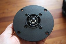
I bought a pair of aluminium dome tweeters SEAS 25 TAF/D (H534-06) in 1993, used them for some years and then stored them for about 20 years. I rediscovered them last summer and did some measurements. On axis frequency response was quite bumpy above 6 kHz and my guess was that the ferrofluid has dried out unevenly and the dome is rocking / tilting at the dampened frequencies.
Resonance frequency according to data sheet should be 1,4 kHz
However impedance curve on data sheet indicates roughly 1,7 kHz
my measurement showed about 2 kHz, maybe because of dry/viscous ferrofluid.
The tweeters were not very usable anymore, so I took the risk and started modifying them to get a usable frequency response and eventually a lower Fs.
Inspiration from troels gravesen
Here is a description of what I did until now:
Required tools:
T20 torx screwdriver
Gaffer tape
Permanent marker
Paper towels and Q-tips
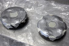
Plastic bags (to protect magnets)
Drill press with sharp metal drill bits and drill lubricating oil
PVA glue
Sine wave generator and amp
Open tweeter:
Mark the position of connectors on the magnet to remember correct assembly! I did not do this and although I am not completely sure I suspect that the parts have one correct fit for exact voice coil centering.
Open the tweeters in a clean enviroment, not in the metal workshop with iron dust and chips everywhere that will be magically attracted into the magnet gap.
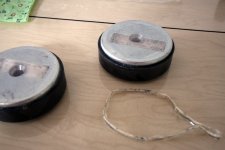
Using a T20 torx screwdriver I carefully loosened the front screws, first turning each screw only half a rotation or one and always changing to the opposite screws. Once all screws were removed it was possible to carefully lift the front plate with the glued on diaphragm and voice coil.
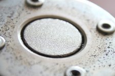
The the aluminium domes are quite soft and any dent will produce horrible resonances at high frequencies. Do not ask how I know this – anyway, it was possible to fix it, but there may be some remaining permanent damage.
Be careful to avoid any metal particles entering the magnet gap once the tweeter is open! Put the magnet systems in tight plastic bags if you carry them around or if they will be stored.
Removing Ferrofluid:
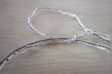
With folded paper and paper towels I removed the ferrofluid from the magnet gap and very carefully also from the voice coil. Q-tips can be helpful here. It may be necessary to repeat this process. I discovered some leftover ferrofluid on the voice coil after some days. Of course, every remaining ferrofluid will affect the impedance curve and frequency response.
Preparation for drilling pole piece:
Store the front plates with domes and voice coils in a safe place with voice coils upwards!
I cleaned the magnet gap and surrounding to allow the protection tape to stick tightly.
Mark the pole piece center with permanent marker for exact drilling – I did not do this and one hole is slightly off center.
I used several sheets of strong gaffer tape to protect the magnet gap from chips and particles. Leave out or cut out the area for drilling, the drill should not grab or lift the protection tape!
Drilling:
Use protective gloves and glasses!
I did not center punch the pole piece as hitting the magnet may damage the magnet or reduce its magnetic flux.
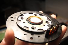
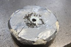
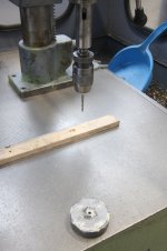
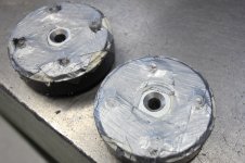
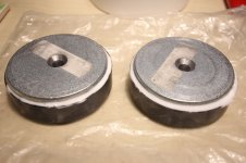
I used a drill press and sharp metal drills to drill the hole, starting with 5 mm then 6 and 8 mm and finally a countersink drill bit on both sides. I used oil to lubricate the drill. Be careful not to soak and loosen the protection tape adhesive with oil. Drill with gentle pressure. Carefully remove chips to avoid them puncturing the protection tape. Use protective gloves to manually hold the magnet. If the drill gets stuck and rotates the magnet let it go and stop the machine to unscrew the drill from the magnet. Do not clamp the magnet, it is much too brittle and will break!
Cleaning the magnet:
I removed as many metal particles by hand as possible, and used adhesive tape to remove particles from the magnet. With more gaffer tape I covered the existing protection tape above magnet gap to enclose all remaining metal particles.
I filled the gaps between ferrite magnet and iron plates with PVA glue. After it has dired I could remove the glue together with metal particles. Only after the magnet element was completely clean I removed all tape layers above magnet gap at once.
Reassembling
(edited 18.05.2021)
Very carefully align the holes in the front plate to the threaded holes of the magnet. The front plate isroughly self centering and will help avoiding damage to the voice coil when joining the two parts. I used a sine signal generator with 1 and 2 kHz and discovered thougt that the “automatic” centering was not enough at all. (i now realized that the distortion came from a small iron chip in the magnet gap!) It makes sense to assemble the parts with the signal playing so you can immediately hear harmonics when the voice coil is touching the pole pieces. I am actually still struggling to get one of the tweeter voice coils centered properly, it seems to work, but once I tighten the screws the “overtones” come back. (this was the iron chip rubbing the voice coil!)
Again, tighten screws in small steps, always changing between opposite screws.
Remember to temporarily cover the new pole piece hole at the bottom of the tweeter to avoid any (magnetic) particles entering the speaker.
Dampening the pole piece hole
I used acousic felt to experiment with stuffing the pole piece hole. This dampens the helmholtz-resonator effect and protects the opening against dust and metal particles entering to the magnet gap. As may be expected and as you will see in the measurement results, the Helmholtz resonator effect of the hole is very pronounced and results in a deep notch, so I will close the tweeters on the back with a metal sheet or MDF and just use the hole as additional air volume which is enough to lower the resonance frequency reasonably.
My next post will include measurements!
Resonance frequency according to data sheet should be 1,4 kHz
However impedance curve on data sheet indicates roughly 1,7 kHz
my measurement showed about 2 kHz, maybe because of dry/viscous ferrofluid.
The tweeters were not very usable anymore, so I took the risk and started modifying them to get a usable frequency response and eventually a lower Fs.
Inspiration from troels gravesen
Here is a description of what I did until now:
Required tools:
T20 torx screwdriver
Gaffer tape
Permanent marker
Paper towels and Q-tips
Plastic bags (to protect magnets)
Drill press with sharp metal drill bits and drill lubricating oil
PVA glue
Sine wave generator and amp
Open tweeter:
Mark the position of connectors on the magnet to remember correct assembly! I did not do this and although I am not completely sure I suspect that the parts have one correct fit for exact voice coil centering.
Open the tweeters in a clean enviroment, not in the metal workshop with iron dust and chips everywhere that will be magically attracted into the magnet gap.
Using a T20 torx screwdriver I carefully loosened the front screws, first turning each screw only half a rotation or one and always changing to the opposite screws. Once all screws were removed it was possible to carefully lift the front plate with the glued on diaphragm and voice coil.
The the aluminium domes are quite soft and any dent will produce horrible resonances at high frequencies. Do not ask how I know this – anyway, it was possible to fix it, but there may be some remaining permanent damage.
Be careful to avoid any metal particles entering the magnet gap once the tweeter is open! Put the magnet systems in tight plastic bags if you carry them around or if they will be stored.
Removing Ferrofluid:
With folded paper and paper towels I removed the ferrofluid from the magnet gap and very carefully also from the voice coil. Q-tips can be helpful here. It may be necessary to repeat this process. I discovered some leftover ferrofluid on the voice coil after some days. Of course, every remaining ferrofluid will affect the impedance curve and frequency response.
Preparation for drilling pole piece:
Store the front plates with domes and voice coils in a safe place with voice coils upwards!
I cleaned the magnet gap and surrounding to allow the protection tape to stick tightly.
Mark the pole piece center with permanent marker for exact drilling – I did not do this and one hole is slightly off center.
I used several sheets of strong gaffer tape to protect the magnet gap from chips and particles. Leave out or cut out the area for drilling, the drill should not grab or lift the protection tape!
Drilling:
Use protective gloves and glasses!
I did not center punch the pole piece as hitting the magnet may damage the magnet or reduce its magnetic flux.
I used a drill press and sharp metal drills to drill the hole, starting with 5 mm then 6 and 8 mm and finally a countersink drill bit on both sides. I used oil to lubricate the drill. Be careful not to soak and loosen the protection tape adhesive with oil. Drill with gentle pressure. Carefully remove chips to avoid them puncturing the protection tape. Use protective gloves to manually hold the magnet. If the drill gets stuck and rotates the magnet let it go and stop the machine to unscrew the drill from the magnet. Do not clamp the magnet, it is much too brittle and will break!
Cleaning the magnet:
I removed as many metal particles by hand as possible, and used adhesive tape to remove particles from the magnet. With more gaffer tape I covered the existing protection tape above magnet gap to enclose all remaining metal particles.
I filled the gaps between ferrite magnet and iron plates with PVA glue. After it has dired I could remove the glue together with metal particles. Only after the magnet element was completely clean I removed all tape layers above magnet gap at once.
Reassembling
(edited 18.05.2021)
Very carefully align the holes in the front plate to the threaded holes of the magnet. The front plate is
Again, tighten screws in small steps, always changing between opposite screws.
Remember to temporarily cover the new pole piece hole at the bottom of the tweeter to avoid any (magnetic) particles entering the speaker.
Dampening the pole piece hole
I used acousic felt to experiment with stuffing the pole piece hole. This dampens the helmholtz-resonator effect and protects the opening against dust and metal particles entering to the magnet gap. As may be expected and as you will see in the measurement results, the Helmholtz resonator effect of the hole is very pronounced and results in a deep notch, so I will close the tweeters on the back with a metal sheet or MDF and just use the hole as additional air volume which is enough to lower the resonance frequency reasonably.
My next post will include measurements!
Attachments
Last edited:
I did rhis with a pair of TW034XO as per Troels writeup, but I didn't drill all the way through the pole piece. My goal was getting the system Q down to 0.7 so the tweeter is better behaved around the resonance. It also reduces the 2k bump quite a bit, almost flattening it out. I used pure wool felt in the cavity for damoing and on top of the pole piece right under the dome. The factory foam doesn't work very well IMO. I taped off the gap with thick aluminum tape, which made cleaning the metal chips a lot easier and kept the gap clean.
The issue with most lower resonance domes is the dual impedance peaks generated by the back chamber and air space behind the VC gap. While a back chamber can help extend the low end cutoff, it doesn't fix the VC gap chamber resonance which can't be mechanically dampened other than by using ferrofluid. There's no good way of getting any damping material into that area. I find that many non-chambered dome tweeters sound better in the lower mids than chambered ones, aside from the higher end models with fancy engineered and shaped chamber designs ei. scan speak and seas. The difference in chamber volumes creates a mechanical compliance issue between the surround and dome surface area and shows itself as increased non linear distortion in some areas around the lower mid frequencies. It also causes airflow issues across the VC gap and the way many manufacturers deal with this is by venting the VC former or by using ferrofluid. Anyways, having just enough back chamber volume just to get the system Q down low enough is really the main goal here. I don't see much point in going lower than 0.6 here because it just reduces lower midrange output.
My modded TW034s sound so much better after drilling out the pole cavities. The difference is quite remarkable and I'm surprised Audax doesn't do it from the factory, other than knowing it will hurt production costs. Coating the dome helps a bit too, but it will take away the rising response that helps the dome play up higher and give it that open sound with a rising response from the breakup modes.
Last edited:
thanks wolf and profiguy!
that's what i would do if I ever did it again!
thanks for your explanation!
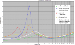
this might be the reason for my little impedance peak at 2,8 kHz!
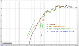
attached my impedance chart of different variants.
for "dampened hole" i filled the drilled hole with acetate felt, without stuffing it completely.
but I didn't drill all the way through the pole piece.
that's what i would do if I ever did it again!
The issue with most lower resonance domes is the dual impedance peaks generated by the back chamber and air space behind the VC gap.
thanks for your explanation!
this might be the reason for my little impedance peak at 2,8 kHz!
attached my impedance chart of different variants.
for "dampened hole" i filled the drilled hole with acetate felt, without stuffing it completely.
Attachments
.. and here come the SPL measurements, done on a 100/50 cm baffle.
the "flush mounted" version could probably be far better, this was just a quick and rough first try, see picture!
conclusions for now:
"helmholtz-resonator" version does not work.
lowering Fs did work.
THD measurements still to be done.
I will also try other dampening experiments.
further optimizations could include a waveguide.
Attachments
Last edited:
You'll probably never be able to completely remove the upper imoedance peak without venting the VC gap from the back, like Troels did with his mods, but the peak will at least have a lower Q and will be less intrusive to response, probably showing less stored energy in that area. I'd like to see the CSD plot before and after. That will really show what's improved overall.
The synthetic felt doesnt really work as well as real wool for damping, but it should reduce the reflections inside the cavity's surfaces and possibly clean up the top end a little. It was wise that you didn't stuff the cavity with the felt, mainly because it will have more of an effect of raising the impedance peak rather than dampening it through slowing down the back wave energy, which lowers the Q of the primary resonance (desirable up until a point).
The synthetic felt doesnt really work as well as real wool for damping, but it should reduce the reflections inside the cavity's surfaces and possibly clean up the top end a little. It was wise that you didn't stuff the cavity with the felt, mainly because it will have more of an effect of raising the impedance peak rather than dampening it through slowing down the back wave energy, which lowers the Q of the primary resonance (desirable up until a point).
Ouch!!! Your drilling an **already magnetized** polepiece gave me the shivers. 
It´s clearly seen how all JUMP straight to the gap and inside of it if tape were not present.
I commercially manufacture speakers from scratch and metal chips are my Nemesis, even being very clean and careful, now and then an almost invisible chip ruins my day or at least 1 speaker.
Sometimes raising its head *after* speaker has been sold, delivered, and mounted/used by Customer, go figure.
PS: FWIW all my polepieces are vented, it costs almost nothing asking the lathe operator to add a final hole through it.
CSD will probably just show a lower resonance, nothing too excitingI'd like to see the CSD plot before and after. That will really show what's improved overall.
The improvement will come from harmonic distortion being way lower (10dB+ improvement) at 1kHz now compared to in the original condition, allowing it to cross much lower.
Another thing to try is that some tweeters have a hemisphere of high density felt that is propped up off the pole piece by standoffs so it sits just behind the dome. In between the standoffs the airflow into the rear chamber is unobstructed and the chamber is filled with a lower density felt/foam.
Last edited:
thanks all for your replies!
in the meantime and after some frustration I discovered that the voice coil is indeed perfectly self-centering and that the distortion was coming from a metal chip in the magnet gap!
I have just installed REW and will do some waterfall and distortion measurements.
the version with ferrofluid cannot be measured, of course, but i have an impulse response done with speaker workshop (I know, I'm old fashioned).
does anyone know how to import this "IMP" file to REW?
it's a text format file in this format:
by the way, the original tweeters did not have any dampening material below the dome. just plain iron ...
in the meantime and after some frustration I discovered that the voice coil is indeed perfectly self-centering and that the distortion was coming from a metal chip in the magnet gap!
I have just installed REW and will do some waterfall and distortion measurements.
the version with ferrofluid cannot be measured, of course, but i have an impulse response done with speaker workshop (I know, I'm old fashioned
). does anyone know how to import this "IMP" file to REW?
it's a text format file in this format:
4096
4096
44099.996393937843
1
-0.000052400283
-0.000044343396
-0.000015839107
-0.000039704583
-0.000018951995
-0.000007995850
-0.000018433181
[...]
0.000110812713
0.000151951666
seas25taf/d6ohm.Pulse
1
12:12:12 01/02/95
0
4095
1.0000000E+00
by the way, the original tweeters did not have any dampening material below the dome. just plain iron ...
so i just installed and used REW for the first time and was suprised how easy i could get my first results!
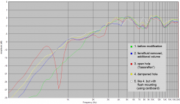
all measurements on baffle 50/100, mic about 40 cm distance, SPL should roughly be correct. all versions flush mounted except for 2)
closing of holes was done with modeling clay.
1) hole closed flush with pole piece surface, similar to original state.

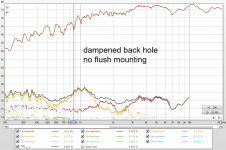
2) back hole open and dampened, no flush mounting
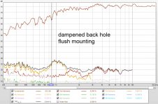
3) back hole open and dampened, flush mounted
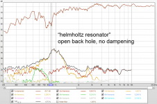
4) back hole open, no dampening: "helmholtz resonator"

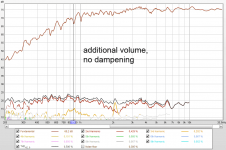
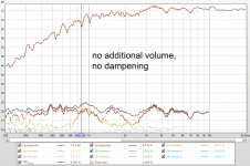
5) pole piece hole closed at back of tweeter (added volume), no dampening

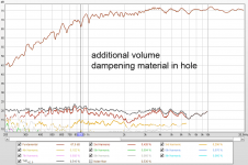
6) pole piece hole closed at back of tweeter (added volume), dampening material in hole

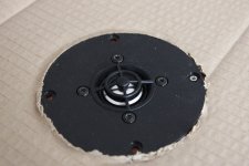
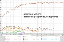
7) pole piece hole closed at back of tweeter (added volume), additional dampening material behind dome, slightly touching dome

SPL and THD (open image for animated GIF):

waterfall (open image for animated GIF):

my conclusions:
so, would I ever do this again?
Removing dried out ferrofluid and ferrofluid in general: definitely.
Adding dampening material behind dome, if there is none: yes!
drilling the pole piece: maybe with such an old tweeter - i would certainly use a larger max drill diameter, to maximize added volume. And I would not drill through the whole pole piece!
Besides adding volume the main advantage of drilling seems to be removing the flat reflective surface behind the dome.
all measurements on baffle 50/100, mic about 40 cm distance, SPL should roughly be correct. all versions flush mounted except for 2)
closing of holes was done with modeling clay.
1) hole closed flush with pole piece surface, similar to original state.
2) back hole open and dampened, no flush mounting
3) back hole open and dampened, flush mounted
4) back hole open, no dampening: "helmholtz resonator"
5) pole piece hole closed at back of tweeter (added volume), no dampening
6) pole piece hole closed at back of tweeter (added volume), dampening material in hole
7) pole piece hole closed at back of tweeter (added volume), additional dampening material behind dome, slightly touching dome
SPL and THD (open image for animated GIF):
waterfall (open image for animated GIF):
my conclusions:
- adding a little back volume to the tweeter obviously extends lower frequency response, but barely noticeable in my case (my drilling hole with 8 mm did just add an estimated 30%).
- the additional hole however reduces distortion and flattens frequency response generally and specially around 3,5 kHz
- adding dampening wool in the additional volume further optimizes response and distortion
- adding even more dampening material that slightly touches the dome raises distortion below resonance frequency.
- keeping “port” open results in a dip in frequency response and a severe peak in distortion at helmholtz resonance. Generally high distortion.
- keeping the port open but dampened results in a flat roll-off but in a peak of distortion at helmholtz resonance and below.
- flush mounting the tweeter (obviously) gives a smoother frequency response above 6 kHz.
- waterfall diagram shows no relevant changes, besides different FR.
so, would I ever do this again?
Removing dried out ferrofluid and ferrofluid in general: definitely.
Adding dampening material behind dome, if there is none: yes!
drilling the pole piece: maybe with such an old tweeter - i would certainly use a larger max drill diameter, to maximize added volume. And I would not drill through the whole pole piece!
Besides adding volume the main advantage of drilling seems to be removing the flat reflective surface behind the dome.
Thanks for doing the experiment and posting
As of:
As of:
I told youin the meantime and after some frustration I discovered that the voice coil is indeed perfectly self-centering and that the distortion was coming from a metal chip in the magnet gap!
I told you
I know, I should have listened to you
however, the iron chip got in the magnet gap quite some time after drilling, probably during changing the dampening material...
The aluminum tape over the gap works well to keep the chips at bay. Once the drilling is done, you just wipe the chips with paper towels wetted with glass cleaner. This works every time for me and there is no need to clean the gap afterwards aside from the usual swipe with masking tape to be sure its clean.
so i just installed and used REW for the first time and was suprised how easy i could get my first results!
all measurements on baffle 50/100, mic about 40 cm distance, SPL should roughly be correct. all versions flush mounted except for 2)
closing of holes was done with modeling clay.
1) hole closed flush with pole piece surface, similar to original state.
View attachment 953164
2) back hole open and dampened, no flush mounting
3) back hole open and dampened, flush mounted
4) back hole open, no dampening: "helmholtz resonator"
View attachment 953165
5) pole piece hole closed at back of tweeter (added volume), no dampening
View attachment 953166
6) pole piece hole closed at back of tweeter (added volume), dampening material in hole
View attachment 953167
7) pole piece hole closed at back of tweeter (added volume), additional dampening material behind dome, slightly touching dome
View attachment 953168
SPL and THD (open image for animated GIF):
View attachment 953169
waterfall (open image for animated GIF):
View attachment 953170
my conclusions:
- adding a little back volume to the tweeter obviously extends lower frequency response, but barely noticeable in my case (my drilling hole with 8 mm did just add an estimated 30%).
- the additional hole however reduces distortion and flattens frequency response generally and specially around 3,5 kHz
- adding dampening wool in the additional volume further optimizes response and distortion
- adding even more dampening material that slightly touches the dome raises distortion below resonance frequency.
- keeping “port” open results in a dip in frequency response and a severe peak in distortion at helmholtz resonance. Generally high distortion.
- keeping the port open but dampened results in a flat roll-off but in a peak of distortion at helmholtz resonance and below.
- flush mounting the tweeter (obviously) gives a smoother frequency response above 6 kHz.
- waterfall diagram shows no relevant changes, besides different FR.
so, would I ever do this again?
Removing dried out ferrofluid and ferrofluid in general: definitely.
Adding dampening material behind dome, if there is none: yes!
drilling the pole piece: maybe with such an old tweeter - i would certainly use a larger max drill diameter, to maximize added volume. And I would not drill through the whole pole piece!
Besides adding volume the main advantage of drilling seems to be removing the flat reflective surface behind the dome.
Can you post the graphs separately instead of a gif? I cant pause the gif to look at each graph properly.
Can you post the graphs separately instead of a gif? I cant pause the gif to look at each graph properly.
yes, I realized the GIF was not the best solution.
I also realized that it's important not to save one new measurement over a set of measurements in REW
I just had to repeat measurements for gated SPL graphs.... see attached!
Attachments
Last edited:
I also made some mod like this. I have sample from totem tweeter that mod in this method that why we cannot use original tw in totem clone . What I get from mod
1. lower fs my original fs is 1400-1500 hz after mod I got 750 hz
2. when remove the ferro fluid you will have more spl a little 1 db
3. I made extend chamber not only close chamber its not enough space to get low fs.
4. sound more relax but not harsh very good for brass percussion instrument . real vivid but smooth
An externally hosted image should be here but it was not working when we last tested it.
An externally hosted image should be here but it was not working when we last tested it.
- Home
- Loudspeakers
- Multi-Way
- SEAS tweeter pole piece drilling