Hello,
I am doing a redesign of the crossover for my speakers, because I was a total noob who had no idea how to design crossovers when I made the pair currently in the speakers.
I did get some great help here in the forum so the original isn't terrible, but I have learned a lot in the 4 years since making the first pair...
So I just would like some advice on the new design.
Here is the original design:


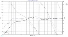
And here is the redesign:


The new design has some compensation for baffle step, along with some padding too...
Do you think there will be any improvement in sound?
Thank you for checking out my post, and possibly giving some help/advice...
I am doing a redesign of the crossover for my speakers, because I was a total noob who had no idea how to design crossovers when I made the pair currently in the speakers.
I did get some great help here in the forum so the original isn't terrible, but I have learned a lot in the 4 years since making the first pair...
So I just would like some advice on the new design.
Here is the original design:
And here is the redesign:
The new design has some compensation for baffle step, along with some padding too...
Do you think there will be any improvement in sound?
Thank you for checking out my post, and possibly giving some help/advice...
Here is a link to the original design thread:
Help with first crossover design - 3 way Eton speakers
Help with first crossover design - 3 way Eton speakers
Here are the files!
View attachment 8_402_C8_32Hex_01.pdf
View attachment 5_200_A8_25Hex.pdf
View attachment 25sd4.pdf
View attachment V17.dxo

I hope these are downloadable!
And again thanks for your help!
View attachment 8_402_C8_32Hex_01.pdf
View attachment 5_200_A8_25Hex.pdf
View attachment 25sd4.pdf
View attachment V17.dxo
I hope these are downloadable!
And again thanks for your help!
The new crossover looks much better.
I recommend measuring the drivers about 60 degrees off axis and plugging those measurements into your crossover simulation, and posting the result here as well. That curve would ideally be flat with a downward tilt, or maybe have a downward tilt at low frequencies and be flat at higher frequencies.
I am currently working on a speaker where the midrange has rising response off axis, which is not ideal. I have compensated for this with a slight downward tilt on axis.
I agree I need to measure the actual drivers in box to get the best crossover, but this thread is mostly to see if I am designing crossovers better now.
I could measure everything very accurately, but if my crossover design techniques are poor, it still will not sound very good.
I was told there are quite a few practices that create a flat response, but may damage amplifiers....
Also my room is very bad for good sound right now, I have seen a video where people measure drivers outside....do you think this is a good idea?
Your design doesn't look bad and for the effort with the chocolate cake you will get some more advice from Lojzek. ")
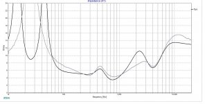
In terms of crossover skills, you have a flat response, the impedance isn't challenging, and the phase angles stay sensible. If you were designing for a low power SE valve amp maybe you would see if you could get a flatter impedance profile.
You probably know this, but look at the response when you flip the midrange driver polarity, and check you nulls. You could tune a bit there possibly, but not too much change. If you can keep to your target crossover frequency and not stress the low end of the midrange you may be able to re tune the two sections for a deeper null. The tune may save you a few $ on component costs if you can reduce component values.
You have to balance the depth of the null, as due to crossover type when you flip back you may get a small bump, therefore you may need to detune slightly from your first re tune. Its one big compromise.
I wouldn't be surprised if you end up dropping tweeter level once you get into the final stages of listening and tweaking.
Measuring outside today in UK would be a pain, cars are going by, the birds are singing and its breezy. I could take everything out side and the neighbour could start cutting the grass.
If all of that was not present, then i could probably get a nice long gate of some 4-5 mS's free of reflections from the garden fence, hedge, house walls etc. That why people sometimes go outside or use a old building late at night when it quieter to get a reflection free measurement free of everyday audio interference.
Careful indoor measurement and sensible placing of mic and loudspeakers should get you reasonable accuracy with measurements down to 500Hz or so.
For a better description See Speaker Measurements 101 Page 3 | Sound & Vision
Whats your favorite kind of chocolate cake?
The one prepared to the best of the baker's abilities.
The grey curves are based on your driver data, and the black ones are based on my simulated data. Crossover parts are intact.
Your data lack phase for all the files but tweeter FR and you had phase derived by XSim only for midrange FR. Use "derive" option in XSim whenever this data is missing. You did not account for cabinet loading, baffle step and diffraction.
Drivers being on a flat vertical baffle means a certain amount of delay for the mid and woofer should be introduced whenever tweeter is the point of reference. Assuming midrange acoustic centre was 1" farther than tweeter, then in "mod delay" of midrange there should be a value of 1". The same for woofer. If it were 2" farther than tweeter, delay would be 2". Because all of these values are zero, it is assumed that all drive units are aligned, which they aren't in reality, unless you did something physically to compensate.
Eton stated that tweeter was measured on a 40x30 cm baffle. This would cause a certain effect on FR of a tweeter being on it, so for the simulation purposes it should be subtracted from the official measurement and at a later point introduced a new one when loudspeaker baffle size and driver position are defined.
Attachments
Last edited:
Ok!
Thank you, Lojzek!
I changed all the drivers to "derived"
Is there a way to find the acoustic centre of a driver...Is it where the voice coil sits, the dust cover, or like half way down the cone? And I assume the tweeter's acoustic centre is at the same spot as the baffle?
To compensate for baffle step, I was shooting for a downward slope of the FR so it's about -3db at the high end...I do know it really has to be measured using the wavelength size and the distance of the mid and tweet from the edge of the baffle...I did the calculation early on in this current crossover design...I think it was 2000hz where it began...
I did set the midrange at +1", and the woofer at +2" and reworked the crossover a bit, I'll have more time tomorrow morning, and then I will post the graphs...
Thanks for your help and schooling on this, I still have a lot to learn...
I made some time to work on this just now, and found a post that says use the voice coil for mod delay measurements...
Looking at my schematic I did of the side view, it looks like the mid sits back about 1" and the woofer 2", so the values you posted are right in line with what the actual measurements are. Again assuming the voice coil is the measuring point.
Another question I have is, do I set the Mod delay at -1" and -2", or +1" and +2"
My little brain says use negative since they sit back from the tweeter...
thanks again!
I agree I need to measure the actual drivers in box to get the best crossover, but this thread is mostly to see if I am designing crossovers better now.
I could measure everything very accurately, but if my crossover design techniques are poor, it still will not sound very good.
I was told there are quite a few practices that create a flat response, but may damage amplifiers....
Also my room is very bad for good sound right now, I have seen a video where people measure drivers outside....do you think this is a good idea?
Haha, ok, I just assumed these were measurements that you had taken.
Optimizing off axis frequency response is a fundamentally important part of crossover design. Without addressing off axis response you can't have "good technique." It's the loudspeaker version of skipping leg day.
Microphones are cheap, you can get a properly calibrated one here for $110:
Cross·Spectrum - Calibrated MiniDSP UMIK-1 Microphones for Sale
With the mic and a free copy of Room EQ wizard you can make gated measurements in your house, the only issue is you can't measure to a very low frequency unless you have a very large room. This is why people measure outside. Room acoustics don't have an effect on gated measurements, just room size.
If you want to read more about why off axis measurements are important, see here:
https://www.harman.com/documents/LoudspeakersandRoomsPt2_0.pdf
There is pdf's online covering topics you are interested in.
White Paper - Accurate In-Room Frequency Response to 10Hz (charlie's audio pages, under FRD response blender)
How to use Passive Crossover Designer to find the relative acoustic offset (techtalk.parts-express...)
XSim convention for delay is + for driver sitting behind the point of reference.
White Paper - Accurate In-Room Frequency Response to 10Hz (charlie's audio pages, under FRD response blender)
How to use Passive Crossover Designer to find the relative acoustic offset (techtalk.parts-express...)
XSim convention for delay is + for driver sitting behind the point of reference.
No need to go back to the drawing board! Just take the measurements with drivers in the cabinet and plug them into your existing design. Measuring speakers is not hard.
I use the Cross spectrum calibrated Dayton EMM-6 mic, Scarlett USB sound card and Arta software, total cost is ~$300. You can see in the link below the Cross spectrum calibration is quite good. The only bad part is they don't answer emails. FYI the USB mic I linked to earlier doesn't work with Arta.
https://www.diyaudio.com/forums/att...emm-6-measurement-mic-comparison-compare1-png
In Arta you can power average your measurements to get the "listening window" and "early reflection" curves described in the PDF I linked to earlier.
- Home
- Loudspeakers
- Multi-Way
- Eton 3-way crossover REDESIGN - need advice