Continuing to my previous ramble: To actually get narrow vertical directivity the waveguide must be larger device than with wide directivity  Simplified: the mouth size relates to frequency where pattern is held and the pattern width relates to depth and mouth size which together determine "the wall angle".
Small vertical dimension of the mouth just moves the pattern control frequency up = more, not less, sound to floor and ceiling at the lower frequencies. Only higher frequencies benefit form small vertical mouth. To even out this narrower mouth the depth would need to increase. Since both horizontal and vertical must share the same throat, the mouth would need to extend further at top and bottom, lips.
Still not sure which one is better, less splash through floor and ceiling on higher frequencies or in the ~1kHz region. It is a lot more easier for acoustic treatment to handle high frequencies so axisymmetric device would be better option in this regard, to hold the vertical pattern to lower frequencies.
Simplified: the mouth size relates to frequency where pattern is held and the pattern width relates to depth and mouth size which together determine "the wall angle". Small vertical dimension of the mouth just moves the pattern control frequency up = more, not less, sound to floor and ceiling at the lower frequencies. Only higher frequencies benefit form small vertical mouth. To even out this narrower mouth the depth would need to increase. Since both horizontal and vertical must share the same throat, the mouth would need to extend further at top and bottom, lips.
Still not sure which one is better, less splash through floor and ceiling on higher frequencies or in the ~1kHz region. It is a lot more easier for acoustic treatment to handle high frequencies so axisymmetric device would be better option in this regard, to hold the vertical pattern to lower frequencies.
Last edited:
I get the point tmuikku, the lobe is tighter but there is still the loose of pattern above XO. I know. To this concern, the predicted in-room response tells the story, on how much vertical excess energy colors the total response. If I had some funds left, I'd try these out:
Product Details
Product Details
Last edited:
I'm sorry didn't mean to preach you, I think you are well into the game and the response you've got looks just fine for the given parts. I thought to write the info and thoughts about the vertical pattern control to help future readers to figure the stuff out. Also clarifies things for myself, which is the main selfish motivation
The current anomalies seen on your measurements are due to crossover frequency being below the patternflip. To get the power and DI smoother around 1kHz either the horn should be bigger, or the woofer should be smaller and c-t-c less, for higher crossover point.
Lets think it through: if the woofer was switched to a smaller one, the now overly large width of the asymmetric horn would make the cabinet bigger than necessary. There goes the only benefit for asymmetric horn (in my opinion) If smooth response over the crossover is a goal a axisymmetric horn would yield smaller cabinet than asymmetric one, since it would optimally be about the same size as the woofer. I can't say if smoother response would sound significantly better, maybe a little at least. To actually get less sound to ceiling and floor, more depth to the horn is the right recipe.
The current anomalies seen on your measurements are due to crossover frequency being below the patternflip. To get the power and DI smoother around 1kHz either the horn should be bigger, or the woofer should be smaller and c-t-c less, for higher crossover point.
Lets think it through: if the woofer was switched to a smaller one, the now overly large width of the asymmetric horn would make the cabinet bigger than necessary. There goes the only benefit for asymmetric horn (in my opinion)
If smooth response over the crossover is a goal a axisymmetric horn would yield smaller cabinet than asymmetric one, since it would optimally be about the same size as the woofer. I can't say if smoother response would sound significantly better, maybe a little at least. To actually get less sound to ceiling and floor, more depth to the horn is the right recipe.
Last edited:
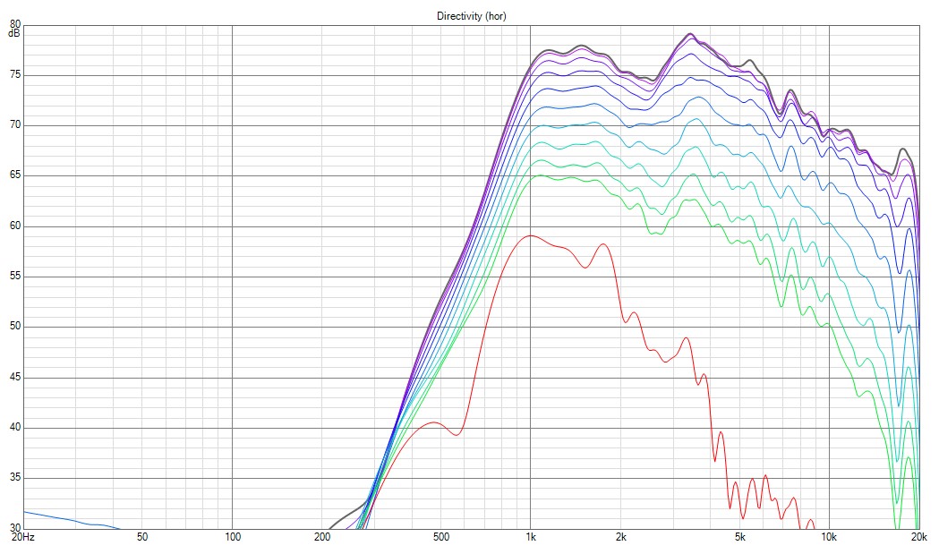
You are welcome to leave any comment here, we are all trying to find th beste compromise possible with limited means to investigate it. I do not consider the area around 1 kHz to be the most problematic, but more the widening centered around 2 and peaking at 2.3 kHz. This widening also happens on horizontal axis btw. The area around 1 kHz is now only slightly lower than response above 2.5 kHz, so almost perfect. Compare to bmc0's results with an axisymmetrical WG, I mean his C-C was something like 32-34 cm but crossed at 1050 Hz.
Still not sure which one is better, less splash through floor and ceiling on higher frequencies or in the ~1kHz region. It is a lot more easier for acoustic treatment to handle high frequencies so axisymmetric device would be better option in this regard, to hold the vertical pattern to lower frequencies.
Well, this is still a bit abstract to my taste. I think it is better to establish thresholds to understand to what degree off-axis excess energy changes our perception of the listening window. Yes, we can see on-axis/listening window and compare it to sound power and early reflexions, ergo in-room response and DI graphs, but this is not enough. I have not had the time to read the early floy toole papers nor his book and search for numbers that help understand to what degree an response is compromized if the off-axis response introduces irregularities. Sure, we can try to find an ideal model where everything is perfect, but I'd rather look for the upper limit of good enough with this specific factor, total directivity.
To get the power and DI smoother around 1kHz either the horn should be bigger, or the woofer should be smaller and c-t-c less, for higher crossover point.
Lets think it through: if the woofer was switched to a smaller one, the now overly large width of the asymmetric horn would make the cabinet bigger than necessary. There goes the only benefit for asymmetric horn (in my opinion)
I am not sure. If I recur what Kimmo said: matching directivity at crossover actually introduces dip-peak in vertical response. And so he adviced on bigger vertical pattern for tweeter than woofer. But we do not know if this can be applied to radiators, because I think he had direct radiators in mind. With a waveguide, there is narrow vertical directivity for everything that is controlled by the walls, and wide for the frequencies where the pattern collapses. It would be beneficial if he could explain his findings for radiators too. BTW, DI of a speaker with bigger waveguide than woofer seems to be a thing: DIYSG HTM-12v1 Speaker Review | Audio Science Review (ASR) Forum, quite well controlled here.
Yep, calling it quits with good enough result is the right way to go. I haven't read the Toole book either. Started few times but fell asleep and forgot the whole book I saw somewhere that turning the speaker on its side would demonstrate the floor/ceiling importance. Not very scientific but should give some indication if it is important or not? Should kill or spark the interest to look for more info at least
Kimmosto has long track record and some of the stuff is clearly gained with experience and are hard to understand (for me). He seems helpful person but motivation seems to be down currently maybe he'll say more if you ask (at the htguide).
The DIYSG speaker you linked to demonstrates the asymmetric waveguide problem I wrote about in the previous post. The woofer is sized for the horn vertical dimension (pattern) for good response and the width of the waveguide is waste of space. It could be replaced with narrower (and shallower) axisymmetric one for similar measured results if my thinking is correct. This in turn would allow smaller baffle and less diffraction problems.
edit. I've got error in the logic. Making the horizontal width narrower on a horn would of course increase directivity as well (or decrease vertical directivity if horn depth was adjusted) so it is not the same thing. Keeping the horizontal directivity wide, vertical narrow and patternflip below crossover frequency requires asymmetric horn with "small" woofer like in the DIYSG example. Gotta read that toole book. At least the summary
I saw somewhere that turning the speaker on its side would demonstrate the floor/ceiling importance. Not very scientific but should give some indication if it is important or not? Should kill or spark the interest to look for more info at least Kimmosto has long track record and some of the stuff is clearly gained with experience and are hard to understand (for me). He seems helpful person but motivation seems to be down currently
maybe he'll say more if you ask (at the htguide).The DIYSG speaker you linked to demonstrates the asymmetric waveguide problem I wrote about in the previous post. The woofer is sized for the horn vertical dimension (pattern) for good response and the width of the waveguide is waste of space. It could be replaced with narrower (and shallower) axisymmetric one for similar measured results if my thinking is correct. This in turn would allow smaller baffle and less diffraction problems.
edit. I've got error in the logic. Making the horizontal width narrower on a horn would of course increase directivity as well (or decrease vertical directivity if horn depth was adjusted) so it is not the same thing. Keeping the horizontal directivity wide, vertical narrow and patternflip below crossover frequency requires asymmetric horn with "small" woofer like in the DIYSG example. Gotta read that toole book. At least the summary
Last edited:
Everybody should read Floyd Toole book particularly the Third Edition as that has been changed quite a lot and is a much better read and reference. But you will not find the answer to those questions there or anywhere else. The recommendation from his research is flat on axis and and smooth off axis trending closer to constant directivity being desirable. That is as specific as it gets. Speakers with a flat DI and those with a rising DI can both rate highly to the point they are hard to pick one over the other in blind testing.I have not had the time to read the early floy toole papers nor his book and search for numbers that help understand to what degree an response is compromized if the off-axis response introduces irregularities. Sure, we can try to find an ideal model where everything is perfect, but I'd rather look for the upper limit of good enough with this specific factor, total directivity.
One thing I have found myself over time is that the music you listen to and attributes of the sound you value the most will heavily dictate which sort of directivity you prefer. Most speakers sound good with Audiophile music and acoustic sources where there is space between the notes so to speak. There will be differences but nothing usually sounds horrible.
If you like rock music or anything with dense harmonic structures then some speakers will just not produce this music well even though they can sound brilliant on other tracks. It's easy to blame the source and say it is "poorly recorded" and go back to the Audiophile tracks where all is well. It is possible to make a speaker that sounds good across a range of different tracks but I have yet to find one that is perfect for all.
The advice on separation distance etc. applies to most speaker concepts and is not solely aimed at direct radiators although not every waveguide will work out perfectly. Matching the directivity at the crossover point is still desirable and if the waveguide is axisymmetric that match will extend to the vertical plane over a much wider range.I am not sure. If I recur what Kimmo said: matching directivity at crossover actually introduces dip-peak in vertical response. And so he adviced on bigger vertical pattern for tweeter than woofer. But we do not know if this can be applied to radiators, because I think he had direct radiators in mind.
Quote: gedlee
But let's not forget that the directivity of the mid-woofer must match that of the waveguide at the crossover. That means that for a given pair of sources the crossover frequency is not variable, but fixed by the selected sources characteristics.
Having the sizes match is not the same as the directivities matching
Quote:
Originally Posted by camplo
One way to do this is to have the dimensions of your woofer and tweeter (horn/wg) match.....another way is to lower the XO to a point that neither driver is directional, rather, wide open.
Quote: gedlee
That will only work in a small number of cases. "Most" horns/waveguides do not have a monotonically falling DI wrt frequency, they have bumps and dips and this will all get baked into the overall DI. The exception is that Marcel showed that he could do a waveguide that had a monotonically falling DI - a fairly unique design. Use that and your good-to-go, almost anything else and this won't work out so well.
I introduced an artificial break due to a damaged usb port on one of my amps (don't ask, please!), but replacement DSP unit is coming on monday and I will then have two chipboard revision 2 speakers to further optimize. Lately, my thoughts had been circling around the waveguide and I am interested in your advice on my last findings about the JBL 90x50 PT-derivates, in my case, Dayton Audio H6512.
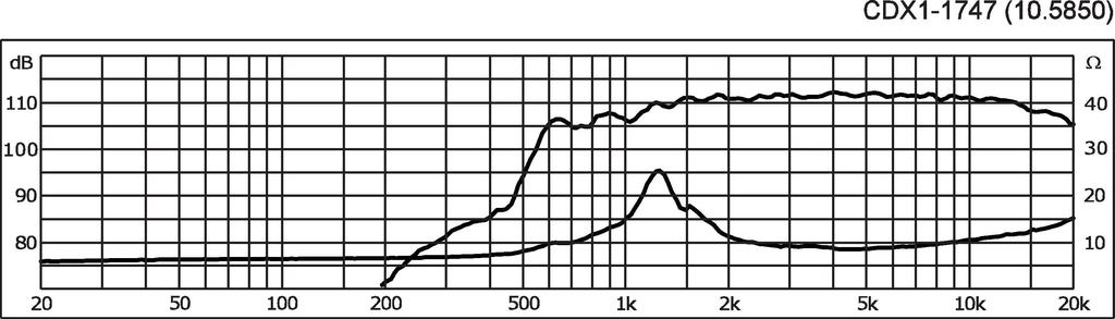
I use the waveguide with Celestion CDX1-1747 and the mother company Monacor gives a FR on their page which is very even all the way down into the lower frequencies (mounted on a 'typical horn') -> Link.
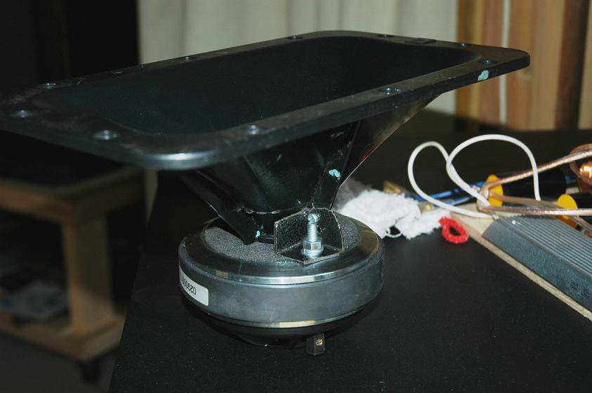
To adapt the driver to the screw-on waveguide, I use the Eminence EB 2 SA adapter:


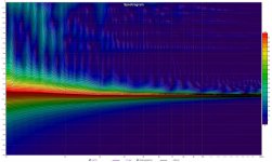
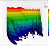
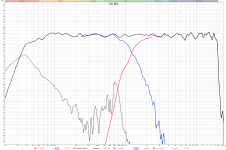
Until now, I was assuming that the single most prominent issue with this waveguide solution was the strong resonance at λ/2 of the EB 2 SA internal diameter, which is at 6.88 kHz and clearly visible in the waterfall plot:

The second issue was the off-axis response peak between 2 and 3 kHz, which was the focus of previous posts in this thread. In this region, I used heavy EQ to fill in a dip in the response already. Now I might be wrong and not only the resonance at 6.88 kHz is a result of the screw-on adapter, but also the response between 2 and 3 kHz. Reverse evidence can be taken from the SEOS-12 measurement by Michael Chua. He shows four plots on his page Denovo Audio SEOS-12 Waveguide (2 Bolt) – AmpsLab, first pair is bolt-mounted flush and second pair is adapted with an Eminence S2BA, the female version of EB 2 SA. Look what is happening with responses.


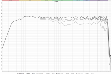
Yes, each time different drivers, but they all follow the same behaviour: long and deep Dip between 2 and 3 kHz, maybe centered around 2.4 kHz which would be an equivalent of λ/4. This behaviour can be seen also in my raw response of Dayton H6512 + CDX1-1747 via EB 2 SA:
So it is fair to say that we are not observing the problem of the waveguide itself, but how it is connected to the compression driver! I had already decided not to change the waveguide at the moment, but was thinking about the obvious resonance at 6.88 kHz for some time and what could be done about it. And remembered that somebody over at Wayne Parham's site once removed the thread on section and straigth-bolted the compression driver to the waveguide: AudioRoundTable.com: Pi Speakers >> Finished Pi 4 with photos

And then, Mike off AmpsLab wrote another test about the combination of the H6512 with a rather small-bore JBL 2414H-C, which has a recommended minimum crossover frequency of 2 kHz. He loves it because there is barely any resonances visible. I could not find a datasheet for the compression driver, but here they say it is 35 Watts AES rated JBL 2414H-C HF Driver is a 1" High Frequency Screw-On Driver, some more pictures of the physical appearance here Link 1 https://www.midwestspeakerrepair.co...-2414h-2414h-1-2414h-c-aftermarket-diaphragm/
and here Link 2 https://reconingspeakers.com/product/jbl-2414h-c-compression-driver-5000169x/
Mike wrote:
Regards
I use the waveguide with Celestion CDX1-1747 and the mother company Monacor gives a FR on their page which is very even all the way down into the lower frequencies (mounted on a 'typical horn') -> Link.
To adapt the driver to the screw-on waveguide, I use the Eminence EB 2 SA adapter:
Until now, I was assuming that the single most prominent issue with this waveguide solution was the strong resonance at λ/2 of the EB 2 SA internal diameter, which is at 6.88 kHz and clearly visible in the waterfall plot:
The second issue was the off-axis response peak between 2 and 3 kHz, which was the focus of previous posts in this thread. In this region, I used heavy EQ to fill in a dip in the response already. Now I might be wrong and not only the resonance at 6.88 kHz is a result of the screw-on adapter, but also the response between 2 and 3 kHz. Reverse evidence can be taken from the SEOS-12 measurement by Michael Chua. He shows four plots on his page Denovo Audio SEOS-12 Waveguide (2 Bolt) – AmpsLab, first pair is bolt-mounted flush and second pair is adapted with an Eminence S2BA, the female version of EB 2 SA. Look what is happening with responses.
Yes, each time different drivers, but they all follow the same behaviour: long and deep Dip between 2 and 3 kHz, maybe centered around 2.4 kHz which would be an equivalent of λ/4. This behaviour can be seen also in my raw response of Dayton H6512 + CDX1-1747 via EB 2 SA:
So it is fair to say that we are not observing the problem of the waveguide itself, but how it is connected to the compression driver! I had already decided not to change the waveguide at the moment, but was thinking about the obvious resonance at 6.88 kHz for some time and what could be done about it. And remembered that somebody over at Wayne Parham's site once removed the thread on section and straigth-bolted the compression driver to the waveguide: AudioRoundTable.com: Pi Speakers >> Finished Pi 4 with photos
And then, Mike off AmpsLab wrote another test about the combination of the H6512 with a rather small-bore JBL 2414H-C, which has a recommended minimum crossover frequency of 2 kHz. He loves it because there is barely any resonances visible. I could not find a datasheet for the compression driver, but here they say it is 35 Watts AES rated JBL 2414H-C HF Driver is a 1" High Frequency Screw-On Driver, some more pictures of the physical appearance here Link 1 https://www.midwestspeakerrepair.co...-2414h-2414h-1-2414h-c-aftermarket-diaphragm/
and here Link 2 https://reconingspeakers.com/product/jbl-2414h-c-compression-driver-5000169x/
Mike wrote:
Wow, yes, that is true. But why is that so? I would consider to try to remove the thread-on section with a saw and create a bolt-on adapter plate and glue it in place. Yet, the JBL Driver with marvelous response also features a duct as an exit to the waveguide. Now I wonder what else I can learn from this, if there might be some other things to consider. Maybe someone can give more insight into this issue.When I tested out the Pyle PH612 in the middle of last year, I couldn’t find any compression drivers that could give me a smooth response. Even the Selenium D220Ti response was too wavy for my liking. That’s why I never did any designs with this horn. It was months later that I chanced upon the JBL JRX212. This model uses the JBL 33800-001 horn with a JBL2414H-C compression driver. Out of curiosity, I bought the JBL 2414H-C. I wanted to see how well this horn works with a dedicated JBL driver. I was stunned when I saw the response. This is one of the best horn/driver combo I’ve ever encountered. She’s flat all the way to 10kHz after which she rolls off gently. It looks like the 338800-001 horn and the 2414H-C were made for each other.
Regards
Last edited:
A compression driver designed with a screw on throat has that as part of the phase plug, it has been designed in.
If you try to adapt a bolt on design to a screw on waveguide the adapter needs to place the exit of the CD directly at the entrance to the horn. If there ends up being a section of straight tube between them you have inserted a helmoholtz resonator in the throat which would account for the cancellation.
Without seeing pictures of how the adaption is done it's hard to comment if this is actually likely to be the reason.
What else do you need to know? According to bmc0 who build his OS-horn around the same compression driver the throat angle of CDX1-1747 is 10°, he writes here: Constant directivity 2-way a la Geddes | Audio Science Review (ASR) Forum The precise data of the EB 2 SA adapter can be seen in pictures in my above post.
It looks like you will be left with a 26mm straight length of tube between the exit of the CD and the start of the horn, if that is what you actually have then it is not a great idea. A combined diffraction slot and hemholtz resonator, probably not what Celestion had in mind to be placed on the exit.
Sure. Btw Earl Geddes once measured for Zilch the combination of this waveguide with Selenium D220Ti B&C Compression Driver and Horns (a nowadays also JBL-branded compression driver) and this is a thread-on driver, where the tubing is as you noted probably accounted for, and there was still some resonance. Not as good as what Michael Chua showed with the original fit JBL driver.

So we can conclude that thread-on adapters are very bad solutions and only the popularity of the concept lend it some relevance, even with other forum users such as gainphile. Until now I have learned the following errors in original Econowave design: Zilch was wrong to to urge a close center-to-center spacing, Geddes was right that it does not matter too much. Secondly, a wider dispersion pattern may even be better than 90x50, for good DI. Anyway, axisymmetric OS seems fine as well. Geddes may have not been right that the JBL PT-waveguide produces excessive resonance due to being a modernized diffraction device, they produced two versions, the flange-mounted and a thread-on, and knew to use the thread-on only with a specially designed compression driver that accounts for the tube resonance. The waveguide geometry itself might actually be pretty fine, as Michael Chua's measurements show and this could be tested when someone provides measurements for the flange-mounted version.
I wonder how I can saw-off the thread on part with some precision and how to glue a flange-mount to the waveguide device.
I wonder how I can saw-off the thread on part with some precision and how to glue a flange-mount to the waveguide device.
So what's the difference between two DSP boards?

One is actually working!
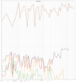
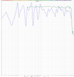
Today my second amp returned to its former grace and the repair got me motivated to remeasure the revision 2 speaker cabinet which is by now fully damped. This means a 2 cm layer of polyester fleece covers the walls and some polyester filling at the top and bottom is put in place to reduce internal modes. just for fun and eye candy reasons, I did some graphs for you all to have something to look at. Btw, I do not now the right conventions for wavelet spectrogramms, this is 1/12th resolution.

Before I applied the full damping which reduced volume quite a bit, I also had cut back the PEQ for bass boost. I will probably reverse this decision, because f3 is now at 40, f6 at 34 and f10 at 30 Hz. I may miss some bass now. The Port resonance is reasonably damped to risk a more aggressive equalization I think.

One is actually working!
Today my second amp returned to its former grace and the repair got me motivated to remeasure the revision 2 speaker cabinet which is by now fully damped. This means a 2 cm layer of polyester fleece covers the walls and some polyester filling at the top and bottom is put in place to reduce internal modes. just for fun and eye candy reasons, I did some graphs for you all to have something to look at. Btw, I do not now the right conventions for wavelet spectrogramms, this is 1/12th resolution.
Before I applied the full damping which reduced volume quite a bit, I also had cut back the PEQ for bass boost. I will probably reverse this decision, because f3 is now at 40, f6 at 34 and f10 at 30 Hz. I may miss some bass now. The Port resonance is reasonably damped to risk a more aggressive equalization I think.
Attachments
Last edited:
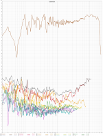
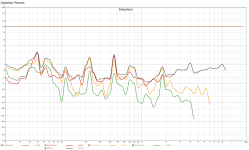
Some more distortion graphs, now it is a stepped sine measurement with 1/6th octave steps. I am not so sure about the dB rating of REW or do not understand it yet. The stepped sine measurement was first done at a loudness setting of the amp that usually produces a 95 dB readout @ 1m (amp at 0 dB, REW at -6 dB). The same value gave me a reported 90 dB in RTA window stepped sine measurement and I decided to set measurement level to -10 dB instead and measure at what the RTA window reports as 86 dB (actually, 85,35 dB). I don't know what's right, it was terribly loud and I left the room.
Graphs attached, distortion peaks seam to coincide/result from room modes?!? ~ at 50-60, 100-120, 220, 450 ...
Graphs attached, distortion peaks seam to coincide/result from room modes?!? ~ at 50-60, 100-120, 220, 450 ...
Attachments
I am a bit confused how I analyze Group Delay in REW. Its graphs seems to be dependent on the gate in Impulse response, I cannot use the window that excludes reflections though, because right window must be >20ms. Then, group delay magnitude fluxes with different windows. Should I always calculate min phase to get a corrected excess group delay plot? And how do I know I do not see room response influencing the result? What is the correct way to set this up?
Using a frequency dependent window will usually give you the best view when the time window isn't big enough to gate but you can't really keep the room out of it. The group delay of a speaker is pretty predictable based on the crossover and alignment of the woofer. Using a nearfield measurement on the woofer would give the greatest room rejection at low frequencies.
Last edited:
- Home
- Loudspeakers
- Multi-Way
- Digital BSC question