So as a long-time lurker in this forum I thought I'd share my latest perhaps stupid idea to gather some feedback from the much more experienced minds of this forum. In the end this is more of a subwoofer topic but it is a multi-way setup so I thought I'd put this here.
Let me start with my current setup:
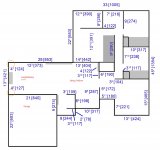
In my "home cinema enhanced" living room have an Atmos 4.2.4 setup (2 subs, phantom center) with the front speakers as pictured and a motorized tension screen (92in) dropping down in-between them.
I found using the phantom center gives me much better sound than any of the center speakers I had ever used in the past since they are never optimally placed and not matching the fronts in construction in a typical living room.
The room itself is a pretty open space (41ft x 14ft x 8ft) and has crawlspace underneath and attic on top so I hardly have problems with room modes.
The front speakers are a custom 3-way active construction consisting of
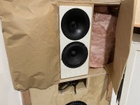
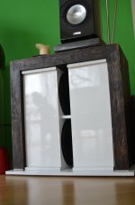
- Vifa XT25 tweeters in waveguide and SB acoustics 6.5in midrange woofer in a very heavy built top cabinet
- 4x Peerless SLS263 10in woofers in a Ripole (dipole bass) configuration built into the stands
- 4x TPA3116 amps (50W per) built in
- miniDSP HD 2x4 for crossover and room correction
Now I'm very happy with how these sound and both the HF waveguide and the dipole bass create a very pleasing sound field with tight bass also very got off axis frequency response.
But in movies unfortunately I can easily get the woofers to reach their limit at scenes with a lot of LF content due to the rather inefficient dipole construction.
So I thought what improvements I could make with also remodeling the front of the room.
And after all movie viewing is maybe 90% of my listening and I could revisit a very "musical" dipole speaker later down the road if my habits change or with a dedicated listening room.
The goals:
The obvious answer would of course be: Move everything into the corners.
Now that's usually a bad idea but if I can do this as a built-in solution (think soffit mounted speakers or baffle wall) I can avoid some of the pitfalls and have many advantages to traditional placement (no baffle step, no SBIR, using the walls as "waveguides", etc.).
I was thinking of something akin to William Cowan's approach for "Unity, The Finale" which seems to have worked well but with an additional curved "false" or decoupled baffle for aesthetic reasons.
The plan:
Keeping the HF and MF section the same cabinet just integrated into the corner I would focus mainly on the LF or subwoofer replacement. A built-in solution would have to be pretty compact and while there are other approaches like infinite baffle subs in the ceiling or crawlspace I would rather avoid additional vents in the ceiling or cutting holes into my hardwood floors and after all WAF plays a huge factor always in living room environments.
Plus I would like to re-use the existing components and avoid bigger expenses other than wood.
TLDR: I was evaluating different subwoofer types in the context of corner placement in roughly 200l volume each and basically narrowed it down to two preferences: 4-8 sealed subs vs. 4 transmission line designs.
I also simulated a regular ported design but it seems to offer no advantages to the upper two.
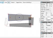
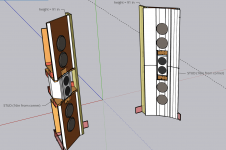
So I went into WinISD and also tried out the excellent TLine program (Leonard Audio?) to simulate my options. Have never attempted Hornresp so far unfortuantely. And in another first I played around with SketchUp to model up a possible TL design, the sealed speakers are straight forward I would say.
Here a few comments from my perspective, feel free to take these half educated assumptions apart. I'm a German so I can take direct criticism")
Sealed design:
Tapered TL design (200sqin to 24sqin):
As you can see from the screenshots the limited TL design I could fit into each of the 4 front corners looks good and offers around 6-8dB more LF volume vs. the sealed simulation but higher delay and some phase "funkyness" between 20 and 30Hz, both of which I doubt I would notice much.
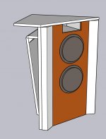
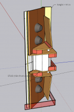
3D model:
Please excuse the otherwise still crude sketchup model, I'm still learning this new software.
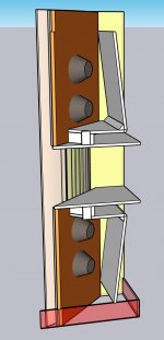
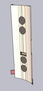
And the folding I chose was with easy wood cuts (not too crazy angles) in mind but could of course be adapted. The sections from the TLine simulation also attached. I noticed stuffing moderately and predominantly in the long sections helps more with a good FR than the rule of thumb of heavy stuffing in the initial section and little to no stuffing at the end but maybe the simulation is not fully accurate here.
The idea with the last section running through the first is optimizing the overall length, coming out the front close to the woofer and that section then also doubling as bracing.
The overall height is 90in and the very top would receive a dedicated cover and above it is the slightly dropped ceiling for the movie screen.
The second port as well as the HF/MF cabinet are not modeled yet and will follow. I plan to stuff all the voids, especially around the HF/MF section with rockwool or similar.
A few questions remain though apart form the general "is this a stupid idea":
So let me know what you guys think... should I give it a try, there would be no going back if I do unless I manage to make a standalone prototype that I could measure free air before I put it into the corner. But either way I'd have to take at least one floor stander irreversibly apart.
Let me start with my current setup:
In my "home cinema enhanced" living room have an Atmos 4.2.4 setup (2 subs, phantom center) with the front speakers as pictured and a motorized tension screen (92in) dropping down in-between them.
I found using the phantom center gives me much better sound than any of the center speakers I had ever used in the past since they are never optimally placed and not matching the fronts in construction in a typical living room.
The room itself is a pretty open space (41ft x 14ft x 8ft) and has crawlspace underneath and attic on top so I hardly have problems with room modes.
The front speakers are a custom 3-way active construction consisting of
- Vifa XT25 tweeters in waveguide and SB acoustics 6.5in midrange woofer in a very heavy built top cabinet
- 4x Peerless SLS263 10in woofers in a Ripole (dipole bass) configuration built into the stands
- 4x TPA3116 amps (50W per) built in
- miniDSP HD 2x4 for crossover and room correction
Now I'm very happy with how these sound and both the HF waveguide and the dipole bass create a very pleasing sound field with tight bass also very got off axis frequency response.
But in movies unfortunately I can easily get the woofers to reach their limit at scenes with a lot of LF content due to the rather inefficient dipole construction.
So I thought what improvements I could make with also remodeling the front of the room.
And after all movie viewing is maybe 90% of my listening and I could revisit a very "musical" dipole speaker later down the road if my habits change or with a dedicated listening room.
The goals:
- bigger movie screen (120-130in) for more immersive experience
- better SPL for LF content (more powerful subs)
- storage (cabinets and floating shelves incl. indirect lighting) around the fireplace
The obvious answer would of course be: Move everything into the corners.
Now that's usually a bad idea but if I can do this as a built-in solution (think soffit mounted speakers or baffle wall) I can avoid some of the pitfalls and have many advantages to traditional placement (no baffle step, no SBIR, using the walls as "waveguides", etc.).
I was thinking of something akin to William Cowan's approach for "Unity, The Finale" which seems to have worked well but with an additional curved "false" or decoupled baffle for aesthetic reasons.
The plan:
Keeping the HF and MF section the same cabinet just integrated into the corner I would focus mainly on the LF or subwoofer replacement. A built-in solution would have to be pretty compact and while there are other approaches like infinite baffle subs in the ceiling or crawlspace I would rather avoid additional vents in the ceiling or cutting holes into my hardwood floors and after all WAF plays a huge factor always in living room environments.
Plus I would like to re-use the existing components and avoid bigger expenses other than wood.
TLDR: I was evaluating different subwoofer types in the context of corner placement in roughly 200l volume each and basically narrowed it down to two preferences: 4-8 sealed subs vs. 4 transmission line designs.
I also simulated a regular ported design but it seems to offer no advantages to the upper two.
So I went into WinISD and also tried out the excellent TLine program (Leonard Audio?) to simulate my options. Have never attempted Hornresp so far unfortuantely. And in another first I played around with SketchUp to model up a possible TL design, the sealed speakers are straight forward I would say.
Here a few comments from my perspective, feel free to take these half educated assumptions apart. I'm a German so I can take direct criticism
Sealed design:
- lower LF performance
- lower physical volume (say around 80l per 2 woofers) - remaining corner cavities could be damped with rockwool
- all drawbacks of sealed design (unwanted resonances, high loading of the driver, big impedance peak, etc.)
- easiest constructions but probably very stiff cabinet needed
Tapered TL design (200sqin to 24sqin):
- better LF performance (although damped and with my volume it nears IB or ported sub behavior)
- effective use of back wave, lower impedance peak and excursion (above 20Hz)
- more complex construction but maybe fun (I love woodworking)
As you can see from the screenshots the limited TL design I could fit into each of the 4 front corners looks good and offers around 6-8dB more LF volume vs. the sealed simulation but higher delay and some phase "funkyness" between 20 and 30Hz, both of which I doubt I would notice much.
3D model:
Please excuse the otherwise still crude sketchup model, I'm still learning this new software.
And the folding I chose was with easy wood cuts (not too crazy angles) in mind but could of course be adapted. The sections from the TLine simulation also attached. I noticed stuffing moderately and predominantly in the long sections helps more with a good FR than the rule of thumb of heavy stuffing in the initial section and little to no stuffing at the end but maybe the simulation is not fully accurate here.
The idea with the last section running through the first is optimizing the overall length, coming out the front close to the woofer and that section then also doubling as bracing.
The overall height is 90in and the very top would receive a dedicated cover and above it is the slightly dropped ceiling for the movie screen.
The second port as well as the HF/MF cabinet are not modeled yet and will follow. I plan to stuff all the voids, especially around the HF/MF section with rockwool or similar.
A few questions remain though apart form the general "is this a stupid idea":
- Is the terminus location on the front baffle close to the woofers good or bad? It should be roughly in phase with the main signal so I would say it doesn't hurt but have sometimes read otherwise in this forum
- How strong would the vibrations be to the structure of the house since I plan on using two walls and the floor as replacements for actual cabinet walls?
- I'm worried the additional 6dB per sub for the corner loading and 12dB for the 4 subs playing in phase would maybe overpower the LF end and lead to too much gain in the 20-100Hz region? In which case the slope of the sealed approach might be enough to get good enough 20Hz SPL?
- Room modes are not really an issue so far but with the design being completely unflexible am I building myself into a corner (pun intended) that I can't get out of? I can do a lot with equalization with the two miniDSPs though.
- I'm slightly worried about the front soundstage moving further apart and the resulting stereo imaging and phantom center although the HF waveguide and the rounded baffle will help a lot I think.
- I could forego the curved baffle for a straight and gain a little more room but it doesn't do much for the FR or SPL.
- Do I couple very rigid to the room's walls (i.e. glued and bolted) or preferably less permanent and somewhat vibration damping, i.e. bolted but with neoprene in-between?
So let me know what you guys think... should I give it a try, there would be no going back if I do unless I manage to make a standalone prototype that I could measure free air before I put it into the corner. But either way I'd have to take at least one floor stander irreversibly apart.
Attachments
-
 floorplan.jpg238.5 KB · Views: 404
 -
 3D_TL_standalone.jpg62.8 KB · Views: 257
 -
 3D_TL_dual.jpg76.2 KB · Views: 227
 -
 3D_TL_baffle.jpg55.7 KB · Views: 226
 -
 TL_enclosure.JPG44.6 KB · Views: 187
 -
 TL_SPL.JPG60 KB · Views: 311
 -
 seal_port_SPL.JPG54.9 KB · Views: 315
 -
 20210217_163230.jpg407.8 KB · Views: 390
 -
 20210217_165453.jpg460.2 KB · Views: 402
My first thoughts were to roll off the ripoles until they can handle the power, then pick it back up with the subs. Closed makes sense there.
You don't necessarily detail how much you plan to rely on the corners with the proposed design, but it does get quite involved. Maybe you could keep it simple by staying with your current needs.
You don't necessarily detail how much you plan to rely on the corners with the proposed design, but it does get quite involved. Maybe you could keep it simple by staying with your current needs.
Thanks for the reply.
The simplest from an audio perspective would of course be to extend the low end but then any other benefits from "getting rid of" the fairly big floor standers don't come into effect (space, screen size, etc.).
After all sound is only a part of the overall puzzle. Due to the size of the floor standers I also couldn't use an AT screen unless I move t he dropped ceiling forward which brings other problems.
Plus building sealed subs while keeping the ripoles would require me to buy additional woofers, not to mention the additional connections I would need to run somehow or split off the floor standards (miniDSP output). I would just complicate things in comparison with a new integrated solution.
I'm sure the peerless woofers would make good sealed woofers but their f3 in a rather small cabinet is not too great for home cinema, unless the corner loading pushes the LF slope substantially up.
If I'd go that route it would probably be via an IB sub manifold with much bigger drivers in the floor or ceiling rather than adding stuff in the corners.
But again, that would be additional equipment that the government (my wife) would frown upon.
Regarding relying ont he corners: The open sides of the 3D model is the actual room corner, meaning there is no side walls in that triangle other than the big shelf unit side (probably a 2x12).
P.S.: I had a high and low pass filter active in the SPL graph from Tline so I removed them to better compare to WinISD in the attached.
I will need a roughly 12Hz high pass to limit driver excursion though and plan to cross the subs over to the MF woofer somewhere in the 100-150Hz region.
With the low pass the "hump" around 100Hz will be flattened but i could also use more dense stuffing inside the TL.
Attachments
Sealed design:
lower LF performance
lower physical volume (say around 80l per 2 woofers) - remaining corner cavities could be damped with rockwool
all drawbacks of sealed design (unwanted resonances, high loading of the driver, big impedance peak, etc.)
easiest constructions but probably very stiff cabinet needed
Tapered TL design (200sqin to 24sqin):
better LF performance (although damped and with my volume it nears IB or ported sub behavior)
effective use of back wave, lower impedance peak and excursion (above 20Hz)
more complex construction but maybe fun (I love woodworking)
sealed vs vented...same volume box.....sealed has lower impedance peak, representing the lower resonance of sealed...wait you are talking pre stuffing....ok after full stuffing, Sealed vs Vented...probably the same (read as very similar) the resonance level considering without stuffing the impedance peak difference is very similar as well.
Last edited:
Going close to corners produces reflections. Making these reflections beneficial is the tricky part, and it varies across the spectrum. You can't put just any speaker in a corner. Especially at lower/middle bass frequencies, the only benefit is the space saving. Gain can be messed up by cancellations.
I feel like I am not sure about sealed vs vented resonance issue until I get somethings cleared up with Horn Resp....
I know a people tend to add aperiodic ports to sealed...if they full stuffing isn't good enough then this would be evidence? Or maybe their box is too small? High qts drivers? I dunno...
I know a people tend to add aperiodic ports to sealed...if they full stuffing isn't good enough then this would be evidence? Or maybe their box is too small? High qts drivers? I dunno...
I don't see a huge benefit to increasing the sealed enclosure much beyond the usually recommended 40ish liters for a single woofer unless I can basically go infinite baffle.
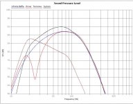
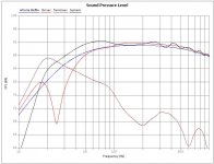
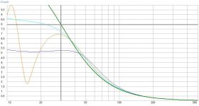
See example attached with two of the woofers in 200l ported (25Hz tuned, orange), 80l sealed (dark blue), 200l sealed (light blue) or basically infinite baffle (I used 2000l sealed, green color).
I would have used the empty space for stuffing outside the box (i.e. filling the rest of the corners with rockwool) if that will help with some back/side wall reflections, although the closed baffle in front should not allow much of that to come through. But in the lowest frequencies due to their wavelength I realistically see no difference that would make.
But based on this I might have reconsidered running the woofers in IB manifolds (that would also minimize vibrations into any structure of the house) if I maybe have a little bit of LF room gain to raise that slope a little more.
I already have a dropped ceiling in the screen area so integration wise it would not be a huge deal, just need to make sure I have enough height in the attic at that position.
Unfortunately the cone excursion (see also attached) for my say 50W per woofer pair would be getting far beyond what the woofers can handle for IB and very close to max for the bigger sealed volume.
These woofers are just not very suitable for IB and I wanted to avoid the additional expenses of other woofers that are.
I also considered venting the complete corner into the attic but simulation wise that would be roughly the same as the vented graph in orange, just with the whole enclosure essentially being a vent (say 96in by 200sqin).
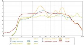
For comparison I also attached the actually measured and uncorrected FR of my Ripole subs in the floor standers but please ignore the absolute SPL values since the mic wasn't calibrated to absolute level.
I had to obviously correct the peak in the 40Hz region which I think is largely caused by my lateral room mode.
But overall I have good LF extension that I want to retain as much as possible with any new design.
The sealed and somewhat the TL design could actually be slightly helped by the room mode in LF extension but the ported design would already peak in that area unless I tune it much lower which brings it close to the IB graph eventually.
So I've basically given up on a ported sub or IB with these woofers here and only kept sealed and TL as contenders if I want to stay with the existing parts.
See example attached with two of the woofers in 200l ported (25Hz tuned, orange), 80l sealed (dark blue), 200l sealed (light blue) or basically infinite baffle (I used 2000l sealed, green color).
I would have used the empty space for stuffing outside the box (i.e. filling the rest of the corners with rockwool) if that will help with some back/side wall reflections, although the closed baffle in front should not allow much of that to come through. But in the lowest frequencies due to their wavelength I realistically see no difference that would make.
But based on this I might have reconsidered running the woofers in IB manifolds (that would also minimize vibrations into any structure of the house) if I maybe have a little bit of LF room gain to raise that slope a little more.
I already have a dropped ceiling in the screen area so integration wise it would not be a huge deal, just need to make sure I have enough height in the attic at that position.
Unfortunately the cone excursion (see also attached) for my say 50W per woofer pair would be getting far beyond what the woofers can handle for IB and very close to max for the bigger sealed volume.
These woofers are just not very suitable for IB and I wanted to avoid the additional expenses of other woofers that are.
I also considered venting the complete corner into the attic but simulation wise that would be roughly the same as the vented graph in orange, just with the whole enclosure essentially being a vent (say 96in by 200sqin).
For comparison I also attached the actually measured and uncorrected FR of my Ripole subs in the floor standers but please ignore the absolute SPL values since the mic wasn't calibrated to absolute level.
I had to obviously correct the peak in the 40Hz region which I think is largely caused by my lateral room mode.
But overall I have good LF extension that I want to retain as much as possible with any new design.
The sealed and somewhat the TL design could actually be slightly helped by the room mode in LF extension but the ported design would already peak in that area unless I tune it much lower which brings it close to the IB graph eventually.
So I've basically given up on a ported sub or IB with these woofers here and only kept sealed and TL as contenders if I want to stay with the existing parts.
Attachments
Are you determined to use the Peerless woofers you already have?
With new woofers you have a lot more freedom, reflex enclosures make a lot of sense if you can keep the crossover low and thus avoid port resonance problems.
My woofers are sealed but subs are reflex for better efficiency, reduced excursion - best of both worlds.
Best wishes
David
With new woofers you have a lot more freedom, reflex enclosures make a lot of sense if you can keep the crossover low and thus avoid port resonance problems.
My woofers are sealed but subs are reflex for better efficiency, reduced excursion - best of both worlds.
Best wishes
David
For now I would like to re-use the Peerless woofers.
I understand I have more options with different woofers (with higher Xmax) but I think with a TL design I would get enough low bass performance for home cinema without fitting much larger woofers somewhere.
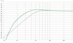
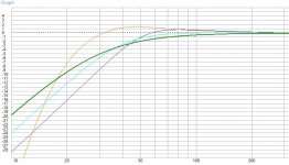
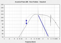
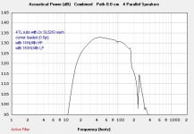
I.e. attached two graphs from hornresp (which I used as a quick sanity check vs. TLine and WinISD). On graph the TL (grey) vs. sealed (black) SPL compared for a single speaker in half space and a 150Hz 4th order low pass roughly indicated via the blue line.
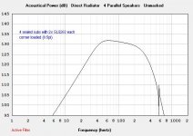
Now moving into eight space (0.5pi) and using 4 such speakers I should be able to get theoretically (not accounting for room correction of course)
- a flat FR around 125dB for approx. 20-150Hz for the TL design (with HP at 18Hz, LP at 150Hz)
- a flat FR around 125dB for approx. 33-300Hz for the sealed design
The TL would need the HP to limit cone excursion and of course I wouldn't need to let both run that high, that's just to illustrate the SPL range.
Phase, group delay, excursion all look good to me then and are very comparable as well as efficiency etc.
That's more volume than I would ever need but obviously the TL has better low end extension but the sealed version is much more straight forward to build and dampen with less potential resonance headaches.
I might even want to think about doing both and going 4way with the TL doing the lowest end only but another crossover would bring other potential problems but also more flexibility with room correction/modes.
EDIT:
One general observation using the three modeling tools mentioned so far (WinISD, TLine, Hornresp):
While FR, SPL, impedance, phase, etc. all look comparable (good!) and of course considering the limitations of the respective tool (like no dampening with hornresp, no corner loading with WinISD, etc.) I consistently get higher excursion values with Hornresp vs. the two others.
Is that normal and which values can I trust?
I understand I have more options with different woofers (with higher Xmax) but I think with a TL design I would get enough low bass performance for home cinema without fitting much larger woofers somewhere.
I.e. attached two graphs from hornresp (which I used as a quick sanity check vs. TLine and WinISD). On graph the TL (grey) vs. sealed (black) SPL compared for a single speaker in half space and a 150Hz 4th order low pass roughly indicated via the blue line.
Now moving into eight space (0.5pi) and using 4 such speakers I should be able to get theoretically (not accounting for room correction of course)
- a flat FR around 125dB for approx. 20-150Hz for the TL design (with HP at 18Hz, LP at 150Hz)
- a flat FR around 125dB for approx. 33-300Hz for the sealed design
The TL would need the HP to limit cone excursion and of course I wouldn't need to let both run that high, that's just to illustrate the SPL range.
Phase, group delay, excursion all look good to me then and are very comparable as well as efficiency etc.
That's more volume than I would ever need but obviously the TL has better low end extension but the sealed version is much more straight forward to build and dampen with less potential resonance headaches.
I might even want to think about doing both and going 4way with the TL doing the lowest end only but another crossover would bring other potential problems but also more flexibility with room correction/modes.
EDIT:
One general observation using the three modeling tools mentioned so far (WinISD, TLine, Hornresp):
While FR, SPL, impedance, phase, etc. all look comparable (good!) and of course considering the limitations of the respective tool (like no dampening with hornresp, no corner loading with WinISD, etc.) I consistently get higher excursion values with Hornresp vs. the two others.
Is that normal and which values can I trust?
Attachments
Last edited:
Wow it's been over a year since that last post but I thought I owe a little build report since I did actually move ahead with this project.
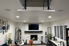
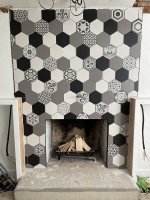
It took quite a while because it was combined with a general remodel of our front living room area that involved tiling the fireplace, building built-in cabinets and floating shelves, cleaning up the ceiling above that area, moving the projector into the ceiling (via lift).
Let me recap the goals I wanted to achieve with the home cinema upgrade:
Meanwhile I built the projector lift in September with a custom kit out of Germany and a 120VAC roller blind motor.
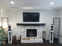
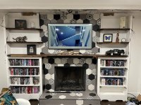
The first picture shows the front of the living room pre remodel with the somewhat cluttered look and the projector lift mid build.
After some initial demo in October 2021 the next steps were
I'm going from previous 92in to now 135in, more than doubling the surface area.
So now early January 2022 I have most everything ready except well, the audio.
The speaker build in the next post.
It took quite a while because it was combined with a general remodel of our front living room area that involved tiling the fireplace, building built-in cabinets and floating shelves, cleaning up the ceiling above that area, moving the projector into the ceiling (via lift).
Let me recap the goals I wanted to achieve with the home cinema upgrade:
- Increase low frequency volume:
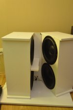
My previous Ripole subwoofers built into the base of my DIY speakers (see picture pre remodel) - while great for music - quickly hit their limit with loud LF content of movies - Increase screen size for more immersive cinema feeling:
The speakers would need to move into the corners but to avoid the pitfalls of such placement I would need to integrate them into a kind of infinite front baffle avoiding back reflections - Maximize the use of available speaker volume:
Which subwoofer technology to use? Sealed, Bass reflex, infinite baffle, transmission line?
Meanwhile I built the projector lift in September with a custom kit out of Germany and a 120VAC roller blind motor.
The first picture shows the front of the living room pre remodel with the somewhat cluttered look and the projector lift mid build.
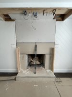
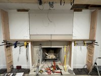
After some initial demo in October 2021 the next steps were
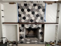
- placing the base structure for the built-ins (2x10 and 2x8) and preparing the fireplace with a lot of cement board
- tiling the fireplace (hexagon tiles vertically are a bitch to do as a first ever tiling project)
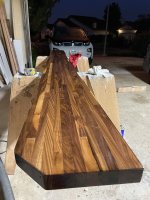
- framing the built-ins and placing the mantel/lower shelf (I used a walnut butcher block countertop)
- running 4ch of speaker wire to each corner hidden in the built-ins (the amps and DSP will be in the base of the cabinets)
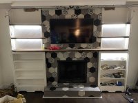
- doing floating shelves with built-in lighting
- putting up the TV (yeah I know - TV too high)
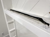
- extending the drop ceiling area above and pulling cable for power, screen control, fiber HDMI to projector lift, etc.
- building shaker doors to the cabinets
I'm going from previous 92in to now 135in, more than doubling the surface area.
So now early January 2022 I have most everything ready except well, the audio.
The speaker build in the next post.
Attachments
-
 01.jpg405.6 KB · Views: 87
 -
 02.jpg430.4 KB · Views: 84
 -
 03.jpg476 KB · Views: 72
 -
 04.jpg501.2 KB · Views: 69
 -
 05.jpg512.9 KB · Views: 73
 -
 06.jpg400.6 KB · Views: 71
 -
 07.jpg439.1 KB · Views: 79
 -
 08.jpg433.9 KB · Views: 76
 -
 09.jpg576.5 KB · Views: 73
 -
 10.jpg553.1 KB · Views: 81
 -
 11.jpg409.5 KB · Views: 77
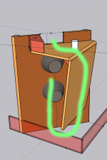
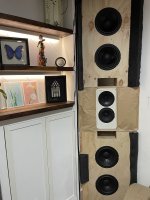
So as mentioned I refined the previously shown sketchup models as attached and kept the idea of the curved baffle.
The woofers are mounted into a straight baffle at 45deg to the walls.
I chose that angle in the end to keep the cuts simpler and because I had good experience with more aggressive toe-in of the front speakers widening the soundstage and sweet spot, plus that will maximize the subwoofer volume.
All in all that will give me 4 corner loaded tapered transmission lines with close to 6cuft of volume each.
The folded path is indicated in green, the room corner of course closes the "tube".
I decided to built the main structure (apart from the aforementioned 2x10s as common side walls) from 3/4 Birch Plywood since I figured coupling to the mass of the large 2x10s, general built-in structure, heavy walnut counter and to the side walls should give me plenty stiffness and killing unwanted cabinet vibrations.
Additionally I used neoprene strips between the major pieces and the surrounding structure to further dampen the transmission of vibrations and close any air gaps.
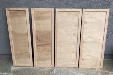
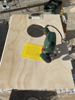
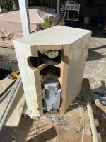
So off I went to buy some wood and cut the baffles and inner dividers as well as proceeded to cut off a corner of my former DIY bookshelf speakers to fit in the later built-ins. Slowly everything came together layer by layer. Cracks a were filled with neoprene and all major edges were caulked, again for air tightness but also bonding to the surrounding structure (apart from wood screws being used).
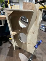
In the end I also added additional stiffening inside the subs via 2x4 pieces because I didn't want to risk that divider vibrating.
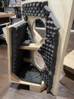
On the inside of the transmission lines I used egg crate foam for the surfaces that could see potential direct reflections and polyfil for the volume in general over approx. the first 2/3 of the length of the line. In the end I used approx. 0.5lb/cuft or a little more but the effect on the measured frequency response was quite small, even compared to no fill (see results in next post).
After creating the mirrored top pieces the full stacks came together. I filled the empty cavities in the mid section with fiberglass insulation for additional dampening around the critical midrange. Finally some additional foam and sealing strips were added in preparation for the thin curved baffle, to prevent that one from vibrating but also introduce the curvature in the first place.
That initial build took about a month to complete (taking me to mid February 2022) with mainly working weekends.
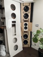
Before the finishing touches the two stacks looked pretty intimidating but early sound tests revealed a lot of clean bass being generated.
But first the proper amplification, crossover and FR or room corrections needed to be done, more on that in the next post.

The woofers are mounted into a straight baffle at 45deg to the walls.
I chose that angle in the end to keep the cuts simpler and because I had good experience with more aggressive toe-in of the front speakers widening the soundstage and sweet spot, plus that will maximize the subwoofer volume.
All in all that will give me 4 corner loaded tapered transmission lines with close to 6cuft of volume each.
The folded path is indicated in green, the room corner of course closes the "tube".
I decided to built the main structure (apart from the aforementioned 2x10s as common side walls) from 3/4 Birch Plywood since I figured coupling to the mass of the large 2x10s, general built-in structure, heavy walnut counter and to the side walls should give me plenty stiffness and killing unwanted cabinet vibrations.
Additionally I used neoprene strips between the major pieces and the surrounding structure to further dampen the transmission of vibrations and close any air gaps.
So off I went to buy some wood and cut the baffles and inner dividers as well as proceeded to cut off a corner of my former DIY bookshelf speakers to fit in the later built-ins. Slowly everything came together layer by layer. Cracks a were filled with neoprene and all major edges were caulked, again for air tightness but also bonding to the surrounding structure (apart from wood screws being used).
In the end I also added additional stiffening inside the subs via 2x4 pieces because I didn't want to risk that divider vibrating.
On the inside of the transmission lines I used egg crate foam for the surfaces that could see potential direct reflections and polyfil for the volume in general over approx. the first 2/3 of the length of the line. In the end I used approx. 0.5lb/cuft or a little more but the effect on the measured frequency response was quite small, even compared to no fill (see results in next post).
After creating the mirrored top pieces the full stacks came together. I filled the empty cavities in the mid section with fiberglass insulation for additional dampening around the critical midrange. Finally some additional foam and sealing strips were added in preparation for the thin curved baffle, to prevent that one from vibrating but also introduce the curvature in the first place.
That initial build took about a month to complete (taking me to mid February 2022) with mainly working weekends.
Before the finishing touches the two stacks looked pretty intimidating but early sound tests revealed a lot of clean bass being generated.
But first the proper amplification, crossover and FR or room corrections needed to be done, more on that in the next post.
Attachments
-
 sketch01.png130.2 KB · Views: 71
 -
 sketch02.png143.5 KB · Views: 73
 -
 sketch03.png158.4 KB · Views: 60
 -
 12.jpg619.4 KB · Views: 63
 -
 13.jpg575.6 KB · Views: 64
 -
 14.jpg578.1 KB · Views: 79
 -
 15.jpg396.5 KB · Views: 69
 -
 16.jpg266.2 KB · Views: 74
 -
 17.jpg543 KB · Views: 68
 -
 18.jpg451.2 KB · Views: 76
 -
 19.jpg442.7 KB · Views: 90
Several things I learned from doing my own corner synergies.
Regarding bass support - that ends at some frequency depending on side wall construction. If side walls are concrete, your 1/8th space corner gain will hold up. Gypsum board/sheetrock, on the other hand, is pretty much transparent to sound at 40 Hz, perhaps even higher. I had woofers breaking in in my garage once and found they were just as loud on the other side of the wall inside my house.
Corner location brings the first reflection points in pretty close to the driver. You would likely benefit from some absorption on the sidewalls adjacent to your coax.
Once you build the speaker in, you can no longer aim/ adjust toe-in, but with a wide beam width, not a problem.
Don't ever move out that house!
@kipman725: The 2 walls of each corner indeed close the subwoofers to those sides.
@nc535: All valid points yes. I do notice there is not much of a gain towards lower frequencies or any noticeable pressure chamber effect (although I assume mainly because the room is a wide open space) compared to say e.g. my old apartment with concrete ceilings and floors.
But I definitely get a volume boost, maybe the stucco on the outside helps here.
On the plus side the room modes are comparatively tame with having both a crawlspace under and an attic above the room.
But I'll show more on these points later with the measurements.
On the first reflections particularly I don't notice any issues (also in measurements) and I think that could be because I'm getting so close to the corners that the first reflections are too shallow angles to reach the listening position directly.
At mid and low frequencies the curved baffle and the walls then start to act more like a big waveguides.
I know this project is pretty much permanently married to the home
I hope I don't have to move out because I'm very happy with the sound and picture.
Alright, build report part 3: Electronics and aesthetics
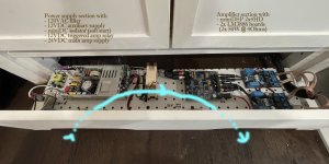
So during the woodwork and rough speaker build I also built the integrated amps into the base of the built-ins.
The attached PDF shows a diagram of the electronics setup around my AVR (Denon X4300h) as the ATMOS/surround centerpiece and bass management which passes the Front Pre-Outs and two Sub Pre-Outs to the the new amps which I essentially re-used from my previous fully active 3-way floor-standers and just re-packaged.
Essentially the 12V trigger from the AVR switches the miniDSP 2x4HD via the miniDC isolator undelayed and then (3s later) via the amp relay the power supply for the amp modules (the diagram is not quite correct here sorry).
I'm using the LM3886 amp modules I'm very happy with (the black/blue YuanJing V2 boards).
Each MF woofer, tweeter and pair of peerless chassis gets up to 50W into its 4Ohm load. That seems low for a subwoofer but as I simulated above it's enough to almost hit the excursion limit with this type of cabinet construction.
With the 4 output channels on the DSP, that of course also serves as the crossover, I could thus do a 4-way active setup for each stack but practically I feed the two subwoofers the same signal for now, making this effectively a 3way active setup.
I might tune this a bit to reduce LF interference (peaks in the bass) but the PEQ I use for room correction (see next post) does a pretty good job at that already.
The slight cuts at the bottom of the baseboards these amps are integrated into are used for the cooling air flow (as indicated in blue in the picture).
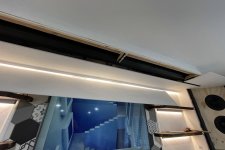
So after the electronics the last step missing was the curved baffle and other aesthetic touches.
First I closed the drop ceiling with covers slotted for the screen to lower through. These also serve for closing the upper subwoofers and I added insulation in the corner above them to again reduce the risk of unwanted vibrations and retain some insulation from the heat in the attic.
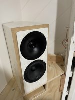
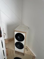
For the purely decorative (decoupled) baffles I used thin 1/4in glossy white coated HDF sheets for those, cutting holes around woofers, mid section and TL ports. You can spot a little mistake making the upper stage a little out of center but it would be covered later anyway.
While the uncovered finished stacks look pretty impressive for the sake of the WAF and because the finish around the woofers and ports was by no means perfect, I decided to add speaker fabric in front.
But how to do that without visible hardware?
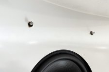
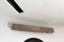
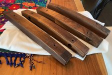
First I routed curved pieces of the same butcher block walnut I used for the shelves and test fit them via these furniture screws you may know from IKEA assemblies to pull onto the baffle without visible hardware.
I fixed the speaker fabric to those pieces and stretch it between one each on top and bottom to look like floating curtains in a way.
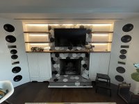
While not perfect in execution I really like how it turned out and the finished front now looks.
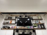
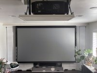
The last picture showing the new living room home theater in its deployed mode (we got used to the massive screen size quickly though).
Oh before there's comments on my missing center:
I had center speakers in the past but found that they never quite matched the fronts in sound signature and were always placed wrong (below or above screen). So I made the switch to using a phantom center long ago and never looked back, never had any issues with dialogue in movies (even stuff like Tenet). But with this remodel I of course considered an acoustically transparent screen.
However the area above the fireplace mantel or shelf would not have offered an adequate space and would somewhat break the aesthetics of the new living room look around the fireplace.
So I decided to stick with the phantom center despite the wider front spacing but the aggressive toe-in, waveguides on the tweeter really help and I have a very wide sweet spot for viewers.
So finally the new 4.4.4 ATMOS living room home theater was finished.
Of course I didn't just do that at risk but took measurements all steps of the way, more on that in the next post.

So during the woodwork and rough speaker build I also built the integrated amps into the base of the built-ins.
The attached PDF shows a diagram of the electronics setup around my AVR (Denon X4300h) as the ATMOS/surround centerpiece and bass management which passes the Front Pre-Outs and two Sub Pre-Outs to the the new amps which I essentially re-used from my previous fully active 3-way floor-standers and just re-packaged.
Essentially the 12V trigger from the AVR switches the miniDSP 2x4HD via the miniDC isolator undelayed and then (3s later) via the amp relay the power supply for the amp modules (the diagram is not quite correct here sorry).
I'm using the LM3886 amp modules I'm very happy with (the black/blue YuanJing V2 boards).
Each MF woofer, tweeter and pair of peerless chassis gets up to 50W into its 4Ohm load. That seems low for a subwoofer but as I simulated above it's enough to almost hit the excursion limit with this type of cabinet construction.
With the 4 output channels on the DSP, that of course also serves as the crossover, I could thus do a 4-way active setup for each stack but practically I feed the two subwoofers the same signal for now, making this effectively a 3way active setup.
I might tune this a bit to reduce LF interference (peaks in the bass) but the PEQ I use for room correction (see next post) does a pretty good job at that already.
The slight cuts at the bottom of the baseboards these amps are integrated into are used for the cooling air flow (as indicated in blue in the picture).
So after the electronics the last step missing was the curved baffle and other aesthetic touches.
First I closed the drop ceiling with covers slotted for the screen to lower through. These also serve for closing the upper subwoofers and I added insulation in the corner above them to again reduce the risk of unwanted vibrations and retain some insulation from the heat in the attic.
For the purely decorative (decoupled) baffles I used thin 1/4in glossy white coated HDF sheets for those, cutting holes around woofers, mid section and TL ports. You can spot a little mistake making the upper stage a little out of center but it would be covered later anyway.
While the uncovered finished stacks look pretty impressive for the sake of the WAF and because the finish around the woofers and ports was by no means perfect, I decided to add speaker fabric in front.
But how to do that without visible hardware?
First I routed curved pieces of the same butcher block walnut I used for the shelves and test fit them via these furniture screws you may know from IKEA assemblies to pull onto the baffle without visible hardware.
I fixed the speaker fabric to those pieces and stretch it between one each on top and bottom to look like floating curtains in a way.
While not perfect in execution I really like how it turned out and the finished front now looks.
The last picture showing the new living room home theater in its deployed mode (we got used to the massive screen size quickly though).
Oh before there's comments on my missing center:
I had center speakers in the past but found that they never quite matched the fronts in sound signature and were always placed wrong (below or above screen). So I made the switch to using a phantom center long ago and never looked back, never had any issues with dialogue in movies (even stuff like Tenet). But with this remodel I of course considered an acoustically transparent screen.
However the area above the fireplace mantel or shelf would not have offered an adequate space and would somewhat break the aesthetics of the new living room look around the fireplace.
So I decided to stick with the phantom center despite the wider front spacing but the aggressive toe-in, waveguides on the tweeter really help and I have a very wide sweet spot for viewers.
So finally the new 4.4.4 ATMOS living room home theater was finished.
Of course I didn't just do that at risk but took measurements all steps of the way, more on that in the next post.
Attachments
Last edited:
Congratulations on having completed an extremely complex build and well done!
re' first reflections, I think the directivity of the coax as waveguide is helping. Can ask what driver you are using?
Looking forward to seeing measurements. That is the other thing about built ins - you can't measure them outdoors.
re' first reflections, I think the directivity of the coax as waveguide is helping. Can ask what driver you are using?
Looking forward to seeing measurements. That is the other thing about built ins - you can't measure them outdoors.
I was out a few days because apparently I got COVID now - yay
Luckily not serious and I can continue here...
Regarding the drivers:
I had measurements somewhere of the tweeter+midrange off axis but can't find them anymore, but they had really good off axis response with the waveguides.
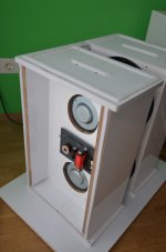
The Ripole subs were always excellent bass wise (the cleanest bass I have heard of all the different sub construction principles), much better then my 2x SVS SB1000 I compared them against. Just the max. volume was really limited for home cinema use.
A few pics and measurements of those from a good while back attached.
Luckily not serious and I can continue here...
Regarding the drivers:
- Tweeter: Vifa XT25 4Ohm in waveguide, not sure which exact sub-version of it though
- Midrange: SB Acoustics SB17NRX35-8
- Bass: 4x Peerless SLS263 8Ohm (always two in parallel)
I had measurements somewhere of the tweeter+midrange off axis but can't find them anymore, but they had really good off axis response with the waveguides.
The Ripole subs were always excellent bass wise (the cleanest bass I have heard of all the different sub construction principles), much better then my 2x SVS SB1000 I compared them against. Just the max. volume was really limited for home cinema use.
A few pics and measurements of those from a good while back attached.
Attachments
So after build (but also many times during) came the measurements.
First things first I wanted to make sure I had no issue with the electrical chain and measured from the TOSLINK input at miniDSP to the amplified output on the LM3886 boards: So far so good, no complaints. I thought I had a measurement with the DAC/ADC conversion included but it was almost transparent, SNR around 90dB nothing to rave about but easily enough for my limited hearing (in the sense that being 90dB above ambient noise is not a good idea anyway long term).

The second picture shows two single subs (LH/RH floor level) without EQ and no add. Polyfill.
Grey overlaid the room simulation in REW showing a particularly nasty room mode around 41Hz that the measurement almost perfectly matches.
Then I fired up the whole 3way arrangement (still on one sub though) and checked how well the automatic PEQ parameters REW calculated fed into miniDSP fared (not good) vs. manual PEQ applied by me in miniDSP (much better).
 .
.

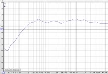
When the full stack was finished on both sides and filling material added I measured both individually with manual PEQ applied from 1m and then stereo at the listening position after running Audyssey from the AVR and tweaking the bass a little where Audyssey had screwed with it.
Obviously more room modes come into play at this position in the middle of the room but so far so good, a decently balanced output from 20Hz up with a house curve, just what I need for home cinema. Maybe I could dial back the reduction towards high frequencies some more but I'm not a huge friend of a bright tuning.
The midrange needs a little more work with the peaks and dips but it's not very noticable even with good quality music and too much tweaking to one position might result in other seating positions suffering again.

So after the initial FR stuff a few more detailed measurements were in order, most at 1m distance from one stack (LH is mostly attached but RH looks almost identical).
The waterfall, GD, decay and phase measurements all looked quite good in my book.
Not much I could do about the sub 40Hz room modes without bulky bass traps (wife would kill me).


Distortion is not perfect but was also hampered a bit by the relatively high noise floor in my living room environment.
But the peak below 30Hz isn't noticeable anyway and above 40Hz all harmonics remained under 0.5%.
I already decreased the gain on my UMIK but couldn't get a good SNR without hitting the limit on the input (and annoying my family with the high volume).
That's also the reason I couldn't do a proper RT60 but with RT30 for example at 80Hz around 100ms I was quite happy.
As explained above, the wood construction of the house with crawlspace below and attic above certainly seems beneficial to reduce reverb in the room at the lowest frequencies.


Finally the clarity values (C50, C80, D50) expectedly were not great since it's a large and completely untreated living room, but not terrible either.
I've seen way worse, especially in the bass region that confirms the tight and clean punch I experience in respective music.
Only the longer reverb in the 70-80Hz muddies that a bit, but those room modes are going to be hard to correct.
A few absorption panels at early reflection points could at least help with the slightly low 300Hz to 2k region (esp. around 1kHz) though.
But I do really not have any problems with speech intelligibility in movies, despite those C50 values and using a phantom center.
 .
.


I'm by no means an expert in these graphs though so feel free to let me know if I'm drawing any wrong conclusions or have hidden issues you would notice.
In the end it's the experience in movies and music that counts for me and especially the former now sounds fantastic with lots of headroom in the bass to make the whole house vibrate nicely without becoming boomy. And that's despite only having around 200W total amp power for the subwoofers! Music sounds good too but of course I made compromises with the quite extreme toe in and corner loading of the subs.
I'd say maybe a tad less musical than my former floorstanders but the additional punch in bass heavy music is also welcome.
Definitely much more "room filling" sound now that also still sounds good about 30ft away in the kitchen/dining area.
First things first I wanted to make sure I had no issue with the electrical chain and measured from the TOSLINK input at miniDSP to the amplified output on the LM3886 boards: So far so good, no complaints. I thought I had a measurement with the DAC/ADC conversion included but it was almost transparent, SNR around 90dB nothing to rave about but easily enough for my limited hearing (in the sense that being 90dB above ambient noise is not a good idea anyway long term).
The second picture shows two single subs (LH/RH floor level) without EQ and no add. Polyfill.
Grey overlaid the room simulation in REW showing a particularly nasty room mode around 41Hz that the measurement almost perfectly matches.
Then I fired up the whole 3way arrangement (still on one sub though) and checked how well the automatic PEQ parameters REW calculated fed into miniDSP fared (not good) vs. manual PEQ applied by me in miniDSP (much better).
.
When the full stack was finished on both sides and filling material added I measured both individually with manual PEQ applied from 1m and then stereo at the listening position after running Audyssey from the AVR and tweaking the bass a little where Audyssey had screwed with it.
Obviously more room modes come into play at this position in the middle of the room but so far so good, a decently balanced output from 20Hz up with a house curve, just what I need for home cinema. Maybe I could dial back the reduction towards high frequencies some more but I'm not a huge friend of a bright tuning.
The midrange needs a little more work with the peaks and dips but it's not very noticable even with good quality music and too much tweaking to one position might result in other seating positions suffering again.
So after the initial FR stuff a few more detailed measurements were in order, most at 1m distance from one stack (LH is mostly attached but RH looks almost identical).
The waterfall, GD, decay and phase measurements all looked quite good in my book.
Not much I could do about the sub 40Hz room modes without bulky bass traps (wife would kill me).
Distortion is not perfect but was also hampered a bit by the relatively high noise floor in my living room environment.
But the peak below 30Hz isn't noticeable anyway and above 40Hz all harmonics remained under 0.5%.
I already decreased the gain on my UMIK but couldn't get a good SNR without hitting the limit on the input (and annoying my family with the high volume).
That's also the reason I couldn't do a proper RT60 but with RT30 for example at 80Hz around 100ms I was quite happy.
As explained above, the wood construction of the house with crawlspace below and attic above certainly seems beneficial to reduce reverb in the room at the lowest frequencies.
Finally the clarity values (C50, C80, D50) expectedly were not great since it's a large and completely untreated living room, but not terrible either.
I've seen way worse, especially in the bass region that confirms the tight and clean punch I experience in respective music.
Only the longer reverb in the 70-80Hz muddies that a bit, but those room modes are going to be hard to correct.
A few absorption panels at early reflection points could at least help with the slightly low 300Hz to 2k region (esp. around 1kHz) though.
But I do really not have any problems with speech intelligibility in movies, despite those C50 values and using a phantom center.
.
I'm by no means an expert in these graphs though so feel free to let me know if I'm drawing any wrong conclusions or have hidden issues you would notice.
In the end it's the experience in movies and music that counts for me and especially the former now sounds fantastic with lots of headroom in the bass to make the whole house vibrate nicely without becoming boomy. And that's despite only having around 200W total amp power for the subwoofers! Music sounds good too but of course I made compromises with the quite extreme toe in and corner loading of the subs.
I'd say maybe a tad less musical than my former floorstanders but the additional punch in bass heavy music is also welcome.
Definitely much more "room filling" sound now that also still sounds good about 30ft away in the kitchen/dining area.
Last edited:
- Home
- Loudspeakers
- Multi-Way
- Corner built-in speakers incl. 4 subs