Hi everyone. I have been playing around on and off in electronics for a good part of the past 6 decades. Now, I have built speakers before but, always with someone else's design and have never built a crossover. Now, I purchased a pair of Dayton DSA115-8 4" mid bass and a bunch of Peerless 811582 tweeters. They were on sale for $4.00 each and in my neck of the woods, you don't find that often. Anyway, as per WinIsd, I designed a small 4.8 Liter vented box with a 1.75" vent. The thing is, I ordered 2 x 2way crossover from China that have their Xover point at 3.2Khz. Now I am having second thoughts. I looked at the parts for the Cnote Xover and to buy all these parts here would cost me close to a cdn Cnote. Hence the China thing. As I was trying to design my Xover in Xsim, I was missing the zma file for the Peerless tweeter and I thought I had a pretty good and simple design. But after learning how to extract the info to get the zma file, nothing I do seems to give me a linear response. I always get a hump in the audible range. I have tried adding and removing coils, caps and resistors to no avail. So I thought I would post my Xsim file here along with the Dayton and Peerless Specs. I would like to try and cross them at 3.2 Khz to use with my Xovers but, I am willing to make some changes. I already added an L pad on the tweeter and a zobel on the woofer. Don't know if they are needed but, I am experimenting. T hank's
Don
Don
Member
Joined 2003
In a little more detail, what you are trying to do with a simulation is to create as close as you can the same conditions that would exist if you put the drivers into the cabinet and then measured it from about 2 - 3' away. That means that the files for each driver have to be manipulated before they go into the xo program.
For the tweeter, that means adding in the baffle diffraction effects from the cabinet. For the mid/woofer that means changing both the FR and impedance response in the LF's due to the effects of the box loading (although that might be considered optional with a 2-way with a high enough xo point). And then adding in the baffle effects as well. Additionally once you get into XSim, you should extract minimum phase ("derived" in the Tune window) for all the files as well as add in the woofer delay that exists because of the different locations of the 2 drivers' acoustic centers.
Have a look at this thread for more detail: So you want to design your own speaker from scratch!
If you are not quite up for that right now, alternatively post the baffle dimensions with the driver position info too and let us know if there is any edge treatment (radius or chamfer?) and give us an idea of speaker placement (out in free space on a stand, up against a wall in a bookshelf, etc) and someone can perhaps set the files up for you.
Just as a learning exercise, in your current xo get rid of the zobel and C4 - you don't need them. The L-pad and the ~3kHz xo frequency are a good idea though. Now increase L2 a tiny bit and C1 a lot in the mid/woofer filter until the response is fairly flat from about 200-2000Hz with a decent roll-off above that. You might experiment with a resistor in series with C1 if you are getting any peaking at the knee of the mid/woofer roll-off and maybe a fairly small capacitor in parallel with L2 if any of the resonances in the HF's still look to be problematic. Questions? Just ask.
On the tweeter, bring the level down by decreasing R2 a fair amount. The other values actually look pretty good.
See if that helps but again note it will just be a learning exercise at this point - different values may make your sim look good but the files are incorrect to start off with so it won't be sounding too good in the real world.
.dxo files are supported natively by the forum.
The woofer Z-offset has not been accounted for with the standard TM layout.
You've also not counted for baffle step, and likely neither has the crossover you bought. This will lead to a very forward sound. Plan for at least 3dB for standard placement in small rooms, and since the woofer is tiny you may need a bit more than you think.
The drivers you have chosen are not easy to work with and not good partners. However you can make it work, sort of, with a woofer on top arrangement (zero acoustic delay) which will help take care of the rising high end that happens when you tilt the tweeter response using the crossover. Since it has a very aggressive rise at the low end, a zobel will help out here - but you might not want to spend as much. A low value shunt across the tweeter input helps to flatten the impedance at the low end, and I prefer to attenuate the signal before going into the filter to help with power dissipation of the crossover components.
The woofer also needs a resonance trap to take care of that ugly peak circa 8.5k (?). I used a 1.2mH coil to get the target baffle step, and a 0.22uF cap across it. You have some small caps going to ground in both the tweeter and woofer circuits, get rid of them. They will not help and the one in the tweeter circuit is plain bad practice.
I've not sorted out the phase response, so treat this as a starting point. Do not use this crossover, it will likely not work that well.
Attachments
Some good choices here. Crossing below 3k, 24dB/oct slopes, rolling down over the hundreds for the baffle.it will likely not work that well.
That tweeter will not be happy below 4k, IMO. I think we still nee a highish crossover, but the woofer is then going to have terrible 3HD above 2.5k, so it's not a happy compromise.
I would suggest the Op do one with a 2.5-2.7k crossover and another with a 3-3.5k XO point. The issue with a high 2/3HD at 2.5k is that it hardens the sound quite a lot at 4-5k, which can be very uncomfortable. For low quality drivers, a bit of polar compromise is needed to balance the on-axis response. It has a narrow sweet spot, but that is a more reasonable compromise.
I haven't heard these drivers, FWIW. But a small cheap tweeter with no rear chamber cannot realistically be used below 3k. Also, this is a woofer on top which doesn't always suit the listening environment, specially for desk mounted unit.
The idea here is to learn and yes, they are not high end. My original idea was to make small speakers to put on my HT ceiling 5.1.4 arrangement without spending a ton of cash and doing it myself.I haven't heard these drivers, FWIW. But a small cheap tweeter with no rear chamber cannot realistically be used below 3k
That was a mouthful right there and, now I see why they pay the engineers the big bucks to design loudspeakers.At the very least, baffle diffraction should be added to the traced response and acoustic delay between drivers included for the simulation to be considered valid.
I will sure read that and in the meantime, since I have already cut the materials, I will assemble the boxes. I will also re read your replies to see if I can understand most of what was said like baffle diffraction and acoustic delay etc. BTW, the finished box size is H11" x W7" x D6" with an interior volume of 306 cu. inches. The drivers and the port will reduce this by about 40 cu. in.Have a look at this thread for more detail: So you want to design your own speaker from scratch!
Don
Baffle diffraction is about what happens when sound waves hit the edges of your cabinet. When the sound wave hits an edge (or an object), depending on it's frequency (ie. the actual size of the wave length), a secondary set of waves gets created. When the 2 sets of waves interact, they create peaks and valleys in the original FR.
True Audio TechTopics: Diffraction Loss
The 6dB of baffle step loss is about the spatial loading of the sound wave. The SPL of any sound wave will be dependent upon the amount of space it is expanding into. Less space means it will be louder. More space means it will be softer. The effect is also frequency dependent - the smaller waves of a speaker's HF's are not large enough to get around the baffle and so they just spread out in a forward direction. The larger waves of the LF's however are big enough to wrap around the cabinet and so they spread out in both forward and backward directions and therefore the HF's will be heard louder than the LF's (by about 6dB depending on frequency).
True Audio Speaker Topics: Spatial Loading
Acoustic delay is about the place on every driver where you can say that the sound wave originates from, referred to as the acoustic center. It's not always correct but usually this is about where the cone or dome of the driver meets the voice coil. Since drivers come in many different sizes, the acoustic centers of the drivers placed on a speaker's baffle are unlikely to be in the same place. This means that the sound waves originating from each driver are not happening at the same time and therefore will probably add together in an undesirable way, again creating either peaks or valleys in the FR at the point of the xo. Luckily, the addition of xo components also changes the timing of a driver's movements but you have to tell XSim what the difference in timing between the 2 drivers is to start off with. You do this by adding the appropriate delay to the woofer.
Hope that helps.
The idea here is to learn and yes, they are not high end. My original idea was to make small speakers to put on my HT ceiling 5.1.4 arrangement without spending a ton of cash and doing it myself.
You have the right idea. I meant to point out the limitations of the drivers, and the resulting compromises that will guide the design of the crossovers.
Any speaker mounted up on a boundary will need almost no baffle step compensation. Also any measurements in free-field or anechoic will likely not be relevant, and neither will a design using traditional methods.
You would likely want to keep dispersion as wide as possible at the expense of distortion, which indicates using the lowest crossover point possible, for this combination that would be around 3k. Maybe 2.8, but no lower or there will be a lot of strain on the tweeters at high output.
Because they are ceiling speakers, a 1mH bass coil will probably be what you need. The rest you can adjust as you see fit. If you're pointing the speaker downwards you should think about which axis you want to optimise the response for. Don't forget to specify the Z-offset (delay).
Good Luck
")
I want to thank you guys for sticking with me an explaining all of this. I am still in the process of reading and trying to understand all that is in wintermute's thread. (slow learner and a lot to swallow) I will also take a look at the links you posted jReave. Unfortunately,I finished building the cabinets yesterday before reading and getting a grasp of all this information. The front baffle is 11" x 7" and I have a little wiggle room to position the speakers. I will take a break today as my tender other has things for me to do.
Don
Don
Too much conjecture for my liking. The article is ignorant of the ways of sound propagation.
Member
Joined 2003
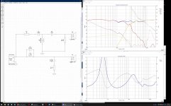
jReave- After reading the article, I think I have an understanding about Baffle diffraction and the way the waves wrap around the baffle. Now it's the 6db loss that I have a problem with. After reading a few articles that suggest 6db attenuation circuit on the mid bass which I simulated here for the calculated values of my driver and enclosure, I can't seem to get any high frequency anymore. I played around with the circuit and nothing seems to bring back the high frequencies. That baffle loss was to model a circuit was it not?
Don
Is this something that is specified by the manufacturer or if I have to figure it out and if so, how?Acoustic delay is about the place on every driver where you can say that the sound wave originates from
Don
Attachments
You know, of the 2 articles I linked to in my previous post, if I was to criticize one as inappropriate for a beginner it would have been the one on Diffraction Loss and not the one on Spatial Loading. I almost added a side note to ignore the circuit diagrams in that article but I didn't want to confuse you at the same time.
There is nothing actually incorrect about them but in practical terms, they are very rarely used today as the method to deal with the baffle diffraction 6dB loss. Instead all you have to do is increase the woofer's series inductor until you more or less get a flat response.
Now in your specific case, you aren't seeing any kind of effect with the parallel L1 and R1 filter because you have just made a very simple XSim wiring mistake - you placed L1 into the circuit on top of the existing wiring so that it has absolutely zero effect. And because the current will always want to go through the path of least resistance, the parallel R1 has absolutely no effect either. So just lift L1 out of the circuit, delete that wire that goes to woofer positive, put L1 back into place and and re-wire the way you have done with L2 in the tweeter circuit which is done correctly.
Once you do that, the circuit should work correctly but, 1 - it won't look right because the woofer FR doesn't include the baffle information yet, and 2 - as I said above, it's not really the way that you want to correct the problem anyways but you're probably not going to understand that until the woofer FR includes the baffle step loss.
Re acoustic center differences, you need to guestimate them for yourself. It's a bit of a simplification but essentially the XSim delay for the woofer is equal to the difference between the acoustic center between the 2 drivers. For the tweeter, the delay is 0. The location of the tweeter acoustic center is generally at about the depth of the faceplate. The location for a coned driver is generally where the diaphragm meets the voice coil. When relying on the spec sheet to figure it out, I simply expand the driver diagram to the correct real size on my computer screen (I find this is easiest done in a Foxit pdf document because it has a user friendly zoom function) - and yes, just measure it on the screen with a ruler - and then measure the distance from the front of the driver to the acoustic center. Technically, this isn't quite correct but for your purposes here with a fairly small speaker, it'll do just fine.
Now that I've got your baffle dimensions, I was going to work up the files for you this afternoon if that makes things a little easier.
That would be great but I am still going to work out the circuit with the explanation you have given me. I will also try to find that acoustic center which is I believe the Z offset referred to by Sangram.Now that I've got your baffle dimensions, I was going to work up the files for you this afternoon if that makes things a little easier.
Don
- Status
- This old topic is closed. If you want to reopen this topic, contact a moderator using the "Report Post" button.
- Home
- Loudspeakers
- Multi-Way
- need help with Xsim