Hello All,
It has been quite some time since I wanted to make this bookshelf design. I chose the Vifa XT-25 and paired it with the 4ohm version of the Peerless 830875 which is the 830510. I cannot find much info on the mids, but went with what I could find.
Since this is my first "from scratch" build I wanted to keep it simple to start with and go from there if needed. So the XO is just a paralleled pair of caps totaling 15.7uf connected in series with the positive side of the tweeter. With the specs on the tweeter imp being 3.4ohms & the mid being 3.85ohms that should give me a XO at approximately 3000Hz.
They sound pretty good, but I have very little experience "voicing" speakers.
I have no testing setup, but instead want to try and help these be as nice as possible without getting too involved in "testing", if possible. I do have more than a handful of parts to mix, match, and swap out for listening tests to help me develop the crossover as I go, but I simply lack direct experience to start jumping just yet.
They are installed in the now discontinued Dayton Curved Enclosures with replaceable baffles. They are a sturdy design with some heft to them. I also added polyfil to the cabinets that are NOT vented. They are being driven by a Denon AVR-X4500H set to 4ohm and everything seems fine so far.
Any thoughts on what I have done so far? Am I missing something or have I done something to this point that could be destructive to the drivers? Again, this is my first set from scratch so I do not want to do anything stupid that will damage them. I have intentionally kept the volume low until I hear some feedback.
Cheers,
David


They look smart.
Getting a Xover right without measurements or testing is next to impossible. I suggest looking for an existing design using the same drivers in a similarly sized cabinet as a starting point but if you want to go it alone a couple of relatively straight forward options are attenuating the tweeter by a few dB with an L-pad arrangement and connecting an inductor in series with the woofer - maybe start with 1.5mH, then listen, remove a few windings if the resulting sound was too hollow, then listen again, repeating the procedure until the mid-range sounds balanced but not too forward.
Getting a Xover right without measurements or testing is next to impossible. I suggest looking for an existing design using the same drivers in a similarly sized cabinet as a starting point but if you want to go it alone a couple of relatively straight forward options are attenuating the tweeter by a few dB with an L-pad arrangement and connecting an inductor in series with the woofer - maybe start with 1.5mH, then listen, remove a few windings if the resulting sound was too hollow, then listen again, repeating the procedure until the mid-range sounds balanced but not too forward.
Hello Tim,
I have been digesting AllenB's fine work ......Introduction to designing crossovers without measurement. In that tutorial he says that one should measure the resistance across the driver, multiply by 1.25 and round to the nearest whole number to get a "baseline" impedance to work with.
View attachment 830875_rev1_0.pdf
View attachment xt25tg30-04_rev1.pdf
Do you know the purpose of the multiplying and rounding? I know that the impedance is not static, like a fixed resistor and that it increases with frequency. But right now I do not know if my XO point, based on the single cap in series with the tweeter, is closer to 2530 or 2975. In the specs I can find the 830875 Nomex mid-range has a serious peak / cone break-up at 4k and I would like to avoid that by at least an octave. I would like to go down as low as I can, say 2k, but I am concerned I may be putting the tweeter at risk of meltdown by doing so.
Thoughts?
Cheers,
David
Last edited:
I think a single cap in series with a tweeter crossing over around 2kHz is pushing it unless you listen only at low levels. In your position I would make a test CD with a swept sine wave going from say 750Hz up to 6kHz in octave ranges on separate tracks and establish the tweeter roll-off that way, by ear. I'd then look at the woofer inductor and set that in the way I mentioned earlier, also trying it in reversed polarity at each stage to check for phase cancellation at Xover.
An alternative might be to listen off axis where the woofer peak becomes flat, run the woofer full range and adjust the treble roll off by ear to suit, however the disadvantage of this over the method I suggested earlier is that it doesn't introduce baffle step compensation and therefore the woofer response will rise with frequency from a point determined by the baffle width.
Seems as though that 830510 is pretty obscure - I can't find any info on it at all.
But if it has about the same FR as the 830875 and if it has about 1/2 the impedance profile, which are pretty big if's actually, then you might want to try the attached xo. This is based on a modeled xo for the 830875 and the XT25 - Peerless 830875 & Vifa XT25.............. -
Techtalk Speaker Building, Audio, Video Discussion Forum - with the appropriate changes for a 4ohm instead of an 8ohm woofer.
No guarantees though but it might be a good starting point. I'm assuming the 4ohm version should play louder than the 8ohm so I reduced R2 from 4ohm down to 1ohm, but this should probably be the 1st component that you'll want to play with. The series impedance flattening notch placed in parallel with the tweeter terminals is essential with that tweeter btw.
Best of luck.
Attachments
I did not see that post, ty jReave!!!!
I have these components in my cart and will order them in short order. Parts Express is out of some, but I can scrounge up the rest out of the bin to make do.
I also have a pair of the 830875's in case I want to try using them instead of the 4ohm version.
Now I will probably be forced to make an external XO box as they will be a challenge to fit inside the enclosure.............hmmmm.
Cheers,
David
A few more questions.......
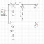
I would like to gain a better understanding as to the purpose that each section in the XO serves and how it interacts with what I hear or experience while listening.
And as such, using the drawing, this is what I "think"......... the series L,C,R networks in parallel to both the woofer and tweeter are conjugate / notch for impedance flattening and control. I also "think" that L3 is controlling the crossover point for the woofer and either C1 or C2 is controlling the tweeter. R2 is contributing to brightness. I do not understand the shunt combination of R1 & L1 or the remaining cap in series with the tweeter positive side.
Tweeter Parts:
XO Control C1-8.2uf
R1-2.0ohm
L1-.35mH
C2-12uf
Brightnness R2-1.0ohm
IMP Conjugate L2-1mH
IMP Conjugate C3-100uf
IMP Conjugate R3-4.0ohm
Mid-Range Parts:
XO Control L3-1.5mH
IMP Conjugate C5-8uf
IMP Conjugate R4-2.0
IMP Conjugate L4-.15mH
It is indicated that appropriate changes were made for a 4ohm instead of an 8ohm woofer. Which changes were affected and why? I am assuming that by lowering R2 the tweeter will bow down to the woofer sensitivity?
I hope this all makes sense. Please help me clarify my "thinking" and correct me or add info as necessary.
Cheers,
David
Last edited:
C1 and C2 along with L1 form a 3rd order high pass filter for the tweeter.R1 fine tunes the slope. R2 controls tweeter sensitivity, the components to its right are likely there to dampen an impedance hump at resonance. It's more effective with drivers without ferro fluid as the fluid dampens the peak.
L3 forms a 1st order Low pass filter, the other components connected in the bass section are a notch filter to control a HF peak I suspect.
L3 forms a 1st order Low pass filter, the other components connected in the bass section are a notch filter to control a HF peak I suspect.
Last edited:
In preparation for the XO work to be as simple as possible I have constructed a pair of Crossover Engineering/Prototype Boards.


Now I just need to add a second pair of binding posts to the rear of the enclosures and wire each driver and polarity to their own dedicated posts.
And of course a set of wires to connect the speakers to the prototype board.
Good times for sure!!!
Cheers,
David
Now I just need to add a second pair of binding posts to the rear of the enclosures and wire each driver and polarity to their own dedicated posts.
And of course a set of wires to connect the speakers to the prototype board.
Good times for sure!!!
Cheers,
David
If anyone else has any thoughts I would like to hear them.
Since you have the Peerless 830875 too, I would go with that one.
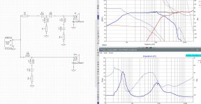
I just did a sim to double check the PE xo with that driver and it looks good.
In comparison, there are just a few too may "if's" involved with the other one. If you want a xo that does that 4ohm driver justice, you should really measure both the FR and impedance with the driver in the cabinet. You can play around with sims and xo parts until your heart's content but there's no guarantee to get it right without starting with the correct data, ie. the measured responses.
I concur with TimA's analysis of the xo. Additionally, you can almost always tell the difference between a notch filter aimed at a driver's resonance peak vs somewhere else by the rather large value(s) that they require - 100uF for the tweeter for eg in this case.
Because the xo wasn't diagramed in that thread (only described), I wasn't exactly sure where R2 needed to be placed. The description seemed to suggest that it go after the tweeter xo but when I did the sim, it works better if it's before the xo. Pic attached.
In terms of going from an 8ohm driver to a 4ohm driver, theoretically that means that you need to reduce an inductor by 1/2 and increase a capacitor by 2. However, when I manipulate the 830875's impedance to approximately match a 4ohm version (ie. reduce the whole thing from about 6ohm nominal down to 3ohm nominal), the FR doesn't end up as nice as the the original xo with the 830875. And that's if the 4ohm version has a similar FR and if it has about the same impedance just reduced in value right across the frequency spectrum. Like I said, that's a lot of if's. I played with that xo for a while and I did get something that looked good but I had to change the method of attach slightly. I could post it as a starting point but this time I am hesitant to do so because again, just a few too many if's involved.
Attachments
Thank you both for your insight. I always understand something better when it is broken down into to digestible chunks.
Considering all the "if's", I will go with the 830875 and see how that works. I just had these laying around and thought I would give them a try since the impedance matched the tweeter. I think they were originally used for a center channel since they are shielded and I may have the XO and parts for it still. Bonus there.
I have heard there is a "newer" version of the 830875 that is somehow different than the oldskool ones I have but at least I will be able to make more if I like them.
I am looking forward to getting this fired up............


Regarding the 100uf cap in the tweeter section. That is one expensive puppy if I were to go with the Dayton metallized polypropylene capacitors.
Dayton Audio DMPC-100 100uF 250V Polypropylene Capacitor
Are there any thoughts on the brand, quality, or specs I should be using for this purpose? Does this size cap in this application need to cost so much? Is there a "philosophy" regarding which types of caps to use in different crossover applications?
Cheers,
David
Check out the size of that thing too. The big values can get a little large.
With this tweeter, most people would be happy with an npe, a non-polarized electrolytic capacitor. A few would not. The big drawback is that they have a limited lifespan of only about 15-20 years. So replacement would be necessary down the road some time.
I believe Parts Express used to carry some but they have recently updated their website and there are actually no npe's listed on the npe page!! Try Madisound instead.
With this tweeter, most people would be happy with an npe, a non-polarized electrolytic capacitor. A few would not. The big drawback is that they have a limited lifespan of only about 15-20 years. So replacement would be necessary down the road some time.
I believe Parts Express used to carry some but they have recently updated their website and there are actually no npe's listed on the npe page!!
Try Madisound instead.Thank you sir!!!
Regarding coils, I have often read in all manner of forums, if the coil will be used in series that it should be as low a DCR as reasonably possible. Espesciallly if there is also a resistor involved in that series. Also, if the coil will be in parallel across the driver that DCR is less important. I have also read that if it will be used in the woofer circuit that the largest gauge will produce tighter "bass".
Am I understanding correctly? What leads one to chose one type of cap or gauge of wire for an air-core inductor over another?
Or where can I go on the net to find such info? I am not much interested in audio foolery and this poses an issue when it comes to choosing parts or trying to learn.
I was going to order Jantzen 20ga. air-core inductors for all of the coils in this XO. Is this a good choice?
Cheers,
David
A Jantzen 3mH 20ga inductor has a DCR of 1.38ohm which is too high. You do indeed want to keep the series resistance in front of a woofer as low as you can. Go with an iron cored inductor instead with a DCR somewhere around .2 or .3ohm.
Remember that DCR adds together when in series. So looking at your xo, all the shunt lines to ground have both an inductor and a resistor in series. So the total resistance of each shunt line is the sum of each line's inductor R and resistor R. Which is great because it means that you can buy inductors with the highest resistance values, which are always the cheapest because they use less copper, and then just make sure that the resistors you get will add up to the correct total DCR for each series combination.
So for eg., the DCR of each coil in the sim I posted was set at .35ohm. If you found coils instead that had DCR's of 1.35ohm, they would all be fine as long as you just reduced each series resistor value by 1 ohm. And in these shunt lines, if you are off by a .2ohm or .3ohm here and there, it probably won't make any difference. If you know how to use XSim, I can attach my file and you can see for yourself how a change in component value affects the results.
In terms of all xo component choices, I personally try to keep the money I spend on them consistent with the value of the drivers themselves. But if you want to go crazy, have at her. In terms of different caps, Humble Hifi probably put up the most comprehensive analysis on the web but remember, it's just 1 person's subjective experience.
- Status
- This old topic is closed. If you want to reopen this topic, contact a moderator using the "Report Post" button.
- Home
- Loudspeakers
- Multi-Way
- New Build.......XT25 & 830875