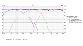
In September 2022 I made a completely fresh set of full polar measurements, vertical and horizontal, and new near-field responses. I re-did the merging of NF with the gated polar responses. Thankfully my new measurements were very close to the old ones.
I have continued to refine the DSP filtering for this system, based on things I learned from my other project: https://www.diyaudio.com/community/threads/new-project-tower-3-way-with-twin-8s.378223/
As well as things I have learned from our discussions with @vineethkumar01 and @tktran303
For this phase of development, I decided to put more emphasis on Predicted In Room response (PIR).
This system has a center-to-center spacing between mid and tweeter of about 0.75 x wavelength. This is not optimal, and as I acknowledged earlier in the thread, I made this decision before I had the knowledge I have today. Now we know that a CTC spacing of about 1.2 x wavelength can lead to a better result when using a non-waveguide tweeter.
Nonetheless, I found that it is possible to achieve a good power response and a good PIR curve even with a non-optimal CTC spacing. It was necessary for me to relax the on-axis requirement from +/- 1 dB to a less restrictive +/- 2 dB.
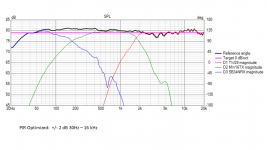
The natural directivity of the tweeter at 10k showed me that a -1.2 dB/octave slope in PIR should be achievable. With this goal, I was able to apply some subtle EQ to get the PIR curve within 1 dB of this target goal, and yet still keep the on-axis response flat within +/- 2 dB. The results look quite good on paper.
How does it sound? Compared to baseline, it sounds very similar. It took me a while to get accustomed to how the two filters sounded different. The baseline filter can have a certain “hardening” of the sound on piano notes in the upper registers, and on soprano voice. The PIR-optimized is “sweeter” on those same notes. On the other hand, the baseline can have, with the right recording, an impression of spaciousness that is slightly wider. These are small differences, the kind that are only apparent with certain recordings.
For now, I think I like the PIR-optimized better, so I have been listening to that one.
I have continued to refine the DSP filtering for this system, based on things I learned from my other project: https://www.diyaudio.com/community/threads/new-project-tower-3-way-with-twin-8s.378223/
As well as things I have learned from our discussions with @vineethkumar01 and @tktran303
For this phase of development, I decided to put more emphasis on Predicted In Room response (PIR).
This system has a center-to-center spacing between mid and tweeter of about 0.75 x wavelength. This is not optimal, and as I acknowledged earlier in the thread, I made this decision before I had the knowledge I have today. Now we know that a CTC spacing of about 1.2 x wavelength can lead to a better result when using a non-waveguide tweeter.
Nonetheless, I found that it is possible to achieve a good power response and a good PIR curve even with a non-optimal CTC spacing. It was necessary for me to relax the on-axis requirement from +/- 1 dB to a less restrictive +/- 2 dB.
The natural directivity of the tweeter at 10k showed me that a -1.2 dB/octave slope in PIR should be achievable. With this goal, I was able to apply some subtle EQ to get the PIR curve within 1 dB of this target goal, and yet still keep the on-axis response flat within +/- 2 dB. The results look quite good on paper.
How does it sound? Compared to baseline, it sounds very similar. It took me a while to get accustomed to how the two filters sounded different. The baseline filter can have a certain “hardening” of the sound on piano notes in the upper registers, and on soprano voice. The PIR-optimized is “sweeter” on those same notes. On the other hand, the baseline can have, with the right recording, an impression of spaciousness that is slightly wider. These are small differences, the kind that are only apparent with certain recordings.
For now, I think I like the PIR-optimized better, so I have been listening to that one.
Attachments

Nice experiment. I like that you give also listening differences, not only graphs...that is really precious. Regarding, "harder" and "softer" sound, before you had small "BBC hill" at 3kHz, now there is wide "BBC dip" from 2-4 kHz...and of course much smoother graphs without jumps...
What about general soundstage, did it move maybe a little bit in some direction with new filter?
Thnaks.
What about general soundstage, did it move maybe a little bit in some direction with new filter?
Thnaks.
hifijim said "This system has a center-to-center spacing between mid and tweeter of about 0.75 x wavelength. This is not optimal, and as I acknowledged earlier in the thread, I made this decision before I had the knowledge I have today. Now we know that a CTC spacing of about 1.2 x wavelength can lead to a better result when using a non-waveguide tweeter."
I'm unclear how this works? I have always thought that closer ctc spacing was better.
I'm unclear how this works? I have always thought that closer ctc spacing was better.
Interesting stuff Jim. I assume most of the benefit for in-room response came from the vertical direction? How do the floor and ceiling reflection compare? What is your ceiling height?
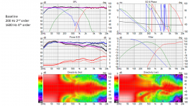
My theory is that, in the PIR-optimized filter, the vertical and horizontal ER responses balance themselves out. My ceiling height is 8'
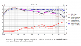
Above is the baseline. The ERDI-horizontal is nice and flat, but the ERDI-vertical has a big peak.
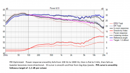
Above is the PIR-optimized. Both ERDI-horizontal and ERDI-vertical are well behaved.
I had a similar thought.Regarding, "harder" and "softer" sound, before you had small "BBC hill" at 3kHz, now there is wide "BBC dip" from 2-4 kHz...and of course much smoother graphs without jumps...
What about general soundstage, did it move maybe a little bit in some direction with new filter?
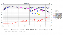
Others have suggested that a rising response from 1k - 3k will add a sense of harshness to the sound, and it doesn't matter if the rise is in the on-axis, the ER response, the power response, the PIR.
In the attached graphic you can see I have a rising response from 1.5k to 2.5k in the power response, ER response, and PIR, but not in the on-axis or listening window. This could explain the slightly "harder" sound I hear on upper register piano and soprano voice. Since the bump is not present in the on-axis, it is not immediately apparent, but it is enough to affect the timbre in a subtle way.
If a designer can get the CTC down to 0.25 x wavelength, then this is best. But even 0.33 x wavelength achieves the same result. But this is rarely possible with normal sized tweeters and mids crossed in the 1.6k - 4k region. So if we can't use an ideal spacing, it seems that 1.2 x wavelength is a good compromise. It is certainly better than 0.75 x wavelength.I'm unclear how this works? I have always thought that closer ctc spacing was better.
There is a thread that discusses this https://www.diyaudio.com/community/...ith-ideal-drivers.380658/page-14#post-7066108
j.
Attachments
I know it is not your usual program material but for testing this sort of difference see if you can find some Iron Maiden to listen to. I have a feeling that the contrast would be more apparent.In the attached graphic you can see I have a rising response from 1.5k to 2.5k in the power response, ER response, and PIR, but not in the on-axis or listening window. This could explain the slightly "harder" sound I hear on upper register piano and soprano voice. Since the bump is not present in the on-axis, it is not immediately apparent, but it is enough to affect the timbre in a subtle way.
If the ceiling is treated properly much of this would disappear as a difference but as most people can't or won't do that it remains.
When I listen to modern (modern to me) rock music, whether it is pearl jam, beastie boys, red hot chili peppers, nirvana, metallica, or soundgarden, I am listening for pure pleasure. I just can't do critical listening. If the lead guitar or vocals sound a bit harsh, hell, aren't they suppose to sound harsh and abrasive? Same is true for the older stuff, creedance, clapton, eagles, rush, zepplin, stones, genesis, and the mighty mighty earth wind & fire... A lot of that stuff was recorded so haphazardly I can never be sure what it is supposed to sound like... EWF excepted as their recording/mastering was excellent. But mostly I just immerse in the music.
I never developed an appreciation for the 80's metal scene... For me, hard rock went off the rails from 1980 to 1990, and then was rebirthed. Kurt Cobain, Eddie Vedder, and Chris Cornell and the rest of them pulled us out of music hell...
But I understand what you are getting at. completely.
j.
I never developed an appreciation for the 80's metal scene... For me, hard rock went off the rails from 1980 to 1990, and then was rebirthed. Kurt Cobain, Eddie Vedder, and Chris Cornell and the rest of them pulled us out of music hell...
But I understand what you are getting at. completely.
j.
To me there is a real difference between it being right and wrong within that same paradigm. There are some tracks on some speakers where it is just downright awful and I cannot listen to it. In general those speakers can sound amazing with Audiophile fare and over time I've come to think that the vertical response is playing a big role in this particular issue.If the lead guitar or vocals sound a bit harsh, hell, aren't they suppose to sound harsh and abrasive?
I don't think so, the only speaker I have had real success so far in this respect is an array with very high vertical directivity. I have got other possible options to try but who knows when they will be completed for a comparison. So either reduce vertical reflections or make them very similar to the direct sound or balance out.
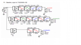
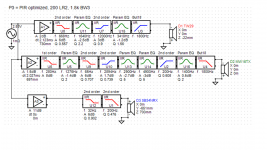
I knew from simulations with ideal drivers and 0.75 CTC that a 3rd order crossover would result in a better sound power response. Because I have the freedom to delay the tweeter, I can use 3rd order butterworth. With a passive crossover in the same situation, I would have probably tried the quasi-3rd order LR, since it works best when the tweeter has 20-40 mm closer acoustic center.
When the spacing is 1.2xwavelength, it is possible to get 2nd and 4th order filters to give a good sound power response.
When the spacing is 1.2xwavelength, it is possible to get 2nd and 4th order filters to give a good sound power response.
I see you got yourself a nice large round over bit. Just be carful using it. It can get very unruly at times and it happens in a split second so keep those fingers clear of the cutters or things can get bloody. Just saying.I made a baffle diffraction simulation with Vituixcad and I showed it in the first post. Since this is an active design, I can compensate for the baffle step easily. But upper-level diffraction (i.e. above 1.5 kHz) is difficult or impossible to compensate for with DSP eq... So my thought is to just minimize diffraction as much as possible. The simulations show that as the radius increases, diffraction effects drop. By the time the radius increases to 30mm or more, diffraction has been almost completely mitigated. Nearly any baffle shape results in a good response if the edge radius is 30 mm or more… rectangular, trapezoidal, elliptical, square, circular, all are good. Bottom line, even though I am using DSP EQ, I think it is important to simulate the baffle to ensure it does not have a diffraction problem which would be difficult to correct later.
Here is a picture of the bit I use… It is a Freud bit, and it performs very well. It is the "Freud 1-1/2" Radius Rounding Over Bit, 1/2" Shank (Quadra-Cut) (34-140)". Highly recommended. When using this bit, we need to use a powerful router and a speed of no more than 12000 RPM. It is so large, it does not fit in the standard base plate of my router table... I had to make a special base plate from plywood with a extra large hole.
j.
")
I’ve seen Kimmosto talk about the 1.2 x wavelength c-c “rule of thumb,” because it better aims lobe nulls to places that are least significant to power response/early reflections (avoiding xo dip/di hump). You say for a non-waveguide tweeter—does the 1.2*wavelength c-c not apply a horn design? Is there a different “rule of thumb” for that? A lot of horn/waveguide designs fall within this larger c-c distance, such as the JBL M2, even when it seems they could push the drivers a bit closer.Now we know that a CTC spacing of about 1.2 x wavelength can lead to a better result when using a non-waveguide tweeter.
I didn't have any experience with waveguide tweeter applications when I wrote that. I am doing my first waveguide project now. So I qualified my statement about 1.2*WL so folks would know I was talking about flat faced tweeters, and that I did not intend the statement to apply beyond that.You say for a non-waveguide tweeter—does the 1.2*wavelength c-c not apply a horn design?
The 1.2*WL rule might apply to waveguide tweeters. Based on my course (simplified) modeling, and measurements of a waveguide tweeter in two different prototype baffles, I think the 1.2*WL rule does work well with waveguides, at least the waveguide I am using at the moment.
j.
Great. I’ll follow your Purifi + Waveguide thread. With larger horns, 1.2xWL c-c can get huge. I was looking at a horn/compression tweeter with a xo of 600hz and 1.2xWL turns out to be about 27”. So there seems a practical limit in normal rooms where your start to get into large seating distances to get proper summation.
Correct—I looked at the M2 schematics and came to the same 1x wavelength calculation. I should have clarified above that kimmosto’s “rule of thumb” is to look in the 1x to 1.4x WL range, with 1.2x WL as a good starting point. So the M2 is in the range that avoids the “worst case” spacing of above ~.4x & below ~1x. At first I thought it an odd choice because it seemed like the designers had room to push the driver closer, but surely their spinorama testing drove them to a similar conclusion as kimmosto.The JBL M2 have about 1x wavelength c-c distance with it's crossover frequency of 800 Hz and geometrical c-c distance of ~43 cm.
- Home
- Loudspeakers
- Multi-Way
- New active Satori Textreme