With some spare time in these days, I realized that it would be nice to share here my last design, built some times ago. So here we have the “Soreta”, an Italian dialectal word meaning sister, as these speakers were destined as a present for my sister.
When I started this design, I had already finished some other 2-way designs, and I was thinking that I could start a 3-way one. So when I saw on eBay a pair of used Monacor SPH-8M drivers at a very low price, I bought them and only after I started to think how to properly use them in a design.
Only one of my past designs was a floorstander, and I found difficult to build it because I don’t have a proper equipped room and gluing together long pieces at right angles was really difficult for me. So for this design I opted for the form factor of the 3w-Classic series of Troels Gravesen, as this is probably the biggest kind of enclosure that I can easily build at home.
For the mid and tweeter I chose Dayton Audio drivers as they are supposed to be of a good quality vs price ratio. For the mid the choice was for the RS125P-8, whereas for the tweeter the choice was for the ND28F-6, based on measurements I have seen.
While I was happy with the mids, I had some problems with the tweeters. One of the tweeters was really out of specs (very high Fs, and FR very different from the other tweeter). I realized the problem after some time after the purchase, because I used until then only the first non defective unit. Unfortunately in August my Italian favorite shop (Audiokit) was closed, so I had to buy in a hurry another couple of tweeters from SoundImports, who sent me ND28FB tweeters instead of the ones I needed (and supposedly bought). So they sent me another couple of tweeters, and they managed to send me another couple of ND28FB instead of the right ones! After that I realized that the only difference was in the faceplate, and I was able to swap them with some effort. But I want to share the fact that on the 6 tweeters I have had, one was really out of spec, one was dead (flat impedance and almost null output), and another one had a different FR. I don’t know if this is bad luck or there is/was a problem in QC, but if you want to copy this design measure at least the impedance of the tweeters.
Anyway, apart the problem with consistency, with the good tweeters the implementation was successful.
Ralf
The enclosure
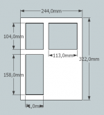
As said, my plan was to build a “classic” 3-way speaker. After some simulations in BDS I ended up with this baffle layout:
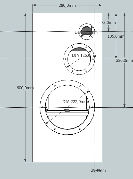
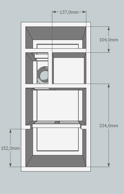
The cabinet depth is 340 mm without baffle, but included the rear panel. The thickness of the external panels is 18 mm, if you use 19 mm (3/4”) doesn’t make much difference. The thickness of the internal braces is 15 mm. The only measure not shown in the following figure is the internal depth of the mid enclosure - 162 mm, so the mid enclosure measures internally 137 mm W x 126 mm H x 162 mm D, for a volume of less than 3L.
I didn’t use a fillet to support the baffle (more on this later), so it is not shown in the figure, but it can be easily added.
From the figure it can also be seen the chosen place for the reflex tube. This is the only sensible place I found where a single tube can be placed (185 mm from top and 73 mm from left of the enclosure). If using my same tube, which needs a fairly large hole, this position is pretty critical.
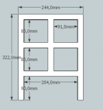
There are three braces, and I think they should be sufficient. Two of them support also the mid enclosure, and the last one is placed at around the mid of the woofer level. The upper braces look like this:

The lower brace is made in this way:
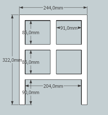
The measures shown here for the lower brace are a suggestion only, and in particular the 90 mm measure depends on the baffle thickness and can be lowered, but make sure that the brace doesn’t touch the back of the woofer. This reason is also why I placed the brace something lower than the exact middle point of the woofer position, as the woofer has a vent on the rear that shouldn’t be blocked.
Ralf
As said, my plan was to build a “classic” 3-way speaker. After some simulations in BDS I ended up with this baffle layout:
The cabinet depth is 340 mm without baffle, but included the rear panel. The thickness of the external panels is 18 mm, if you use 19 mm (3/4”) doesn’t make much difference. The thickness of the internal braces is 15 mm. The only measure not shown in the following figure is the internal depth of the mid enclosure - 162 mm, so the mid enclosure measures internally 137 mm W x 126 mm H x 162 mm D, for a volume of less than 3L.
I didn’t use a fillet to support the baffle (more on this later), so it is not shown in the figure, but it can be easily added.
From the figure it can also be seen the chosen place for the reflex tube. This is the only sensible place I found where a single tube can be placed (185 mm from top and 73 mm from left of the enclosure). If using my same tube, which needs a fairly large hole, this position is pretty critical.
There are three braces, and I think they should be sufficient. Two of them support also the mid enclosure, and the last one is placed at around the mid of the woofer level. The upper braces look like this:
The lower brace is made in this way:
The measures shown here for the lower brace are a suggestion only, and in particular the 90 mm measure depends on the baffle thickness and can be lowered, but make sure that the brace doesn’t touch the back of the woofer. This reason is also why I placed the brace something lower than the exact middle point of the woofer position, as the woofer has a vent on the rear that shouldn’t be blocked.
Ralf
Attachments

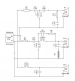
The crossover
After some simulations I settled on this crossover:
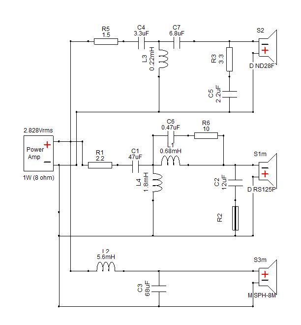
It is a LR2 design between woofer and mid, and due to a crossover point between 450 and 500 Hz a 2nd order electrical network was needed to obtain the correct slopes. Between mid and tweeter it is a LR4 design with asymmetrical slopes in order to compensate for the different acoustic centers. Electrically this is accomplished with a 2nd order network on the mid and a 3rd one on the tweeter. The crossover point is around 3 KHz. On the mid there is also a notch for the breakup that helps also to reach the target slope (C6+R6), on the tweeter the R3+C5 combo tilts down the response. The two resistors R1 and R5 provide the attenuation needed for the mid and tweeter.
DCR of the various coils are: L1 0.4 Ohm, L2 0.35 Ohm, L3 0.35 Ohm, L4 1 Ohm.
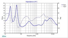
The calculated impedance is shown here, and matches very well with the measured one:

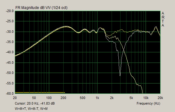
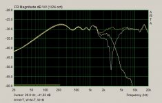
The following figure shows the measured FR of the full speaker, together with the FR with the tweeter reversed to show the reversed null at the crossover point, and also the FR of the mid an woofer alone.
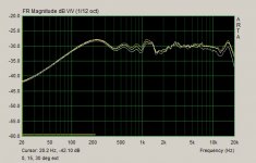
I also have done some off-axis measurements, although only on the horizontal plane. Since the speakers aren’t symmetrical, I pointed the mic at tweeter height but on the middle of the speaker and performed 15 and 30 degree off axis in the two directions. The first image shows what happens when the rotation is in the sense that moves mid and tweeter toward the mic:

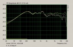
Rotating the speaker in the sense that moves the mid and tweeter further away from the mic yields this:
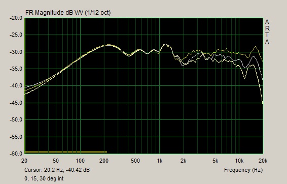
Those measurements indicate that the speakers can be positioned flat or lightly toed in, with the mid and tweeter in the inner position.
Ralf
After some simulations I settled on this crossover:
It is a LR2 design between woofer and mid, and due to a crossover point between 450 and 500 Hz a 2nd order electrical network was needed to obtain the correct slopes. Between mid and tweeter it is a LR4 design with asymmetrical slopes in order to compensate for the different acoustic centers. Electrically this is accomplished with a 2nd order network on the mid and a 3rd one on the tweeter. The crossover point is around 3 KHz. On the mid there is also a notch for the breakup that helps also to reach the target slope (C6+R6), on the tweeter the R3+C5 combo tilts down the response. The two resistors R1 and R5 provide the attenuation needed for the mid and tweeter.
DCR of the various coils are: L1 0.4 Ohm, L2 0.35 Ohm, L3 0.35 Ohm, L4 1 Ohm.
The calculated impedance is shown here, and matches very well with the measured one:
The following figure shows the measured FR of the full speaker, together with the FR with the tweeter reversed to show the reversed null at the crossover point, and also the FR of the mid an woofer alone.
I also have done some off-axis measurements, although only on the horizontal plane. Since the speakers aren’t symmetrical, I pointed the mic at tweeter height but on the middle of the speaker and performed 15 and 30 degree off axis in the two directions. The first image shows what happens when the rotation is in the sense that moves mid and tweeter toward the mic:
Rotating the speaker in the sense that moves the mid and tweeter further away from the mic yields this:
Those measurements indicate that the speakers can be positioned flat or lightly toed in, with the mid and tweeter in the inner position.
Ralf
Attachments
The built (part 1)
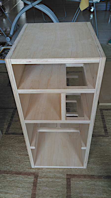
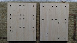
I started the built with the mid enclosure, meaning that the first pieces to be created were the internal braces. This is how I cut the holes in the braces, making first holes with a drill, and then cut the wood with a jigsaw:

Note the small hole in the right piece. This hole is where the mid cable will enter in the enclosure, remember to drill the hole before gluing all the pieces together, as after the cab is built making a hole is difficult.
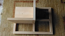
The following photos show the next phase of the mid enclosure built. The small roundover on the holes is for aesthetically reasons only, I highly doubt it will add something sonically. Having a small space for building the speakers means I have to glue one piece at a time.


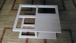
After that all the braces can be glued to the side walls together with the top and bottom panels.
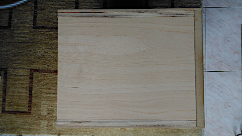
Next I glued the back panel. The last things to do before adding a removable baffle is to add thickness to the panels where appropriate. In case you don’t like the ply pattern in a finished speaker, I found that adding slim panels is essential for the finishing phase, for either a veneer or a paint finish. My plan was to use 15 mm birch ply for anything but the baffle, but I had to resort to a MDF back, if not I had to buy another ply sheet just for the backs. So I ended in building what is seen above in 15 mm birch ply, adding a 18 mm MDF back, and then add 3 mm thin MDF foils first on the sides and then on top and bottom, for an overall external thickness of 18 mm. This is the cab just before the last 3 mm MDF foil was added on the top.
Ralf
I started the built with the mid enclosure, meaning that the first pieces to be created were the internal braces. This is how I cut the holes in the braces, making first holes with a drill, and then cut the wood with a jigsaw:
Note the small hole in the right piece. This hole is where the mid cable will enter in the enclosure, remember to drill the hole before gluing all the pieces together, as after the cab is built making a hole is difficult.
The following photos show the next phase of the mid enclosure built. The small roundover on the holes is for aesthetically reasons only, I highly doubt it will add something sonically. Having a small space for building the speakers means I have to glue one piece at a time.
After that all the braces can be glued to the side walls together with the top and bottom panels.
Next I glued the back panel. The last things to do before adding a removable baffle is to add thickness to the panels where appropriate. In case you don’t like the ply pattern in a finished speaker, I found that adding slim panels is essential for the finishing phase, for either a veneer or a paint finish. My plan was to use 15 mm birch ply for anything but the baffle, but I had to resort to a MDF back, if not I had to buy another ply sheet just for the backs. So I ended in building what is seen above in 15 mm birch ply, adding a 18 mm MDF back, and then add 3 mm thin MDF foils first on the sides and then on top and bottom, for an overall external thickness of 18 mm. This is the cab just before the last 3 mm MDF foil was added on the top.
Ralf
Attachments

The built (part 2)
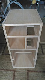
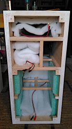
Unfortunately I took very few photos of the built and finishing process. So I’m commenting on some things randomly sometimes with the aid of a photo and sometimes without. The first photo shows a finished cabinet without the baffle:
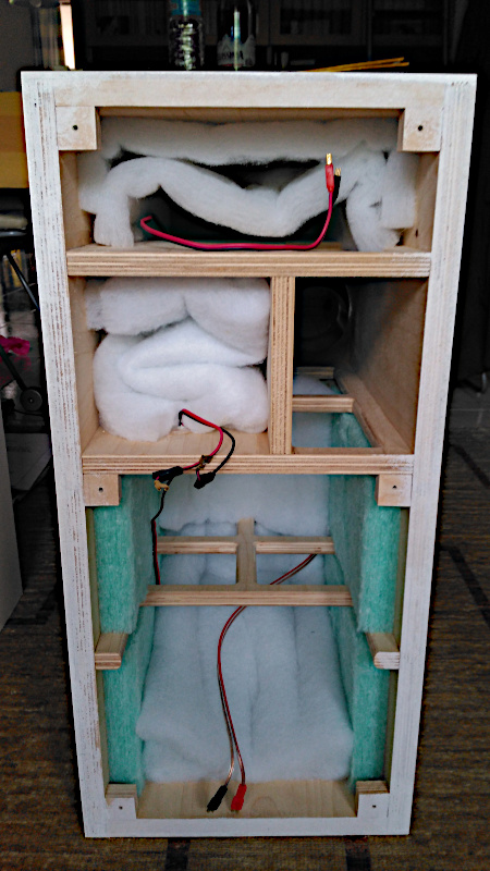
What can be seen here is where I put damping material. The white stuff is Sonofil, the green one is a polyester sheet with a thickness of some 3 cm.
The square wood pieces are where I bolted the baffle to the enclosure. I chose to have a removable baffle because the whole built was - as always - a work in process, and I needed to have access to the internal, remove drivers, measure drivers, tweak the crossover, and so on, so a removable baffle is the best approach. I didn’t use a fillet to support the baffle because with the space and tools I have would have been complicated to have it, so I resorted to gluing 6x 2.5x.2.5 cm birch ply pieces instead. Between the baffle and the cabinet I glued a strip of sealing tape to the baffle.
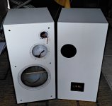
The finished speakers without drivers can be seen here:

The baffle is nothing special, I only chamfered the edges, mainly for aesthetical reasons as the chamfer is too small to provide diffraction benefits. I countersunk the bolts on the baffle so I first drilled a 10 mm wide and 6-8 mm depth hole and then a 5 mm wide hole for the remaining thickness of the baffle.
On the rear I used a flared vent. The exact model is the BR-70HP, shortened by 10 cm, and tunes the enclosure in the low 30s. This is a valid vent, but requires a precise cutout, but by doing so there is no need for screws.
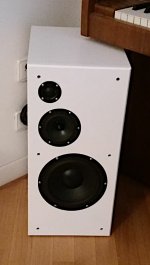
Before painting the speakers I gave a thick layer of primer, sanded down to a flat surface. For finishing I choose a matte varnish and painted the speakers with a roll, one face at a time. The color was dictated by sister’s home decor, mostly white.
The only photo I have for a completed speaker is this one:

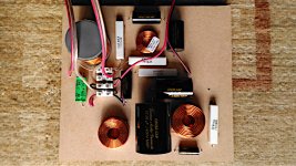
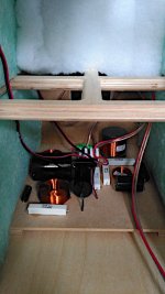
This is the crossover board, built on a 5 mm MDF piece. The components are glued on it and soldered on the rear with a point-to-point method.

And this is the crossover board in place.

On the corners there are 4 feet to provide clearance for the wires under the board, and between the feet and the enclosure I used some blue-tack to secure the board but have it removable.
Ralf
Unfortunately I took very few photos of the built and finishing process. So I’m commenting on some things randomly sometimes with the aid of a photo and sometimes without. The first photo shows a finished cabinet without the baffle:
What can be seen here is where I put damping material. The white stuff is Sonofil, the green one is a polyester sheet with a thickness of some 3 cm.
The square wood pieces are where I bolted the baffle to the enclosure. I chose to have a removable baffle because the whole built was - as always - a work in process, and I needed to have access to the internal, remove drivers, measure drivers, tweak the crossover, and so on, so a removable baffle is the best approach. I didn’t use a fillet to support the baffle because with the space and tools I have would have been complicated to have it, so I resorted to gluing 6x 2.5x.2.5 cm birch ply pieces instead. Between the baffle and the cabinet I glued a strip of sealing tape to the baffle.
The finished speakers without drivers can be seen here:
The baffle is nothing special, I only chamfered the edges, mainly for aesthetical reasons as the chamfer is too small to provide diffraction benefits. I countersunk the bolts on the baffle so I first drilled a 10 mm wide and 6-8 mm depth hole and then a 5 mm wide hole for the remaining thickness of the baffle.
On the rear I used a flared vent. The exact model is the BR-70HP, shortened by 10 cm, and tunes the enclosure in the low 30s. This is a valid vent, but requires a precise cutout, but by doing so there is no need for screws.
Before painting the speakers I gave a thick layer of primer, sanded down to a flat surface. For finishing I choose a matte varnish and painted the speakers with a roll, one face at a time. The color was dictated by sister’s home decor, mostly white.
The only photo I have for a completed speaker is this one:
This is the crossover board, built on a 5 mm MDF piece. The components are glued on it and soldered on the rear with a point-to-point method.
And this is the crossover board in place.
On the corners there are 4 feet to provide clearance for the wires under the board, and between the feet and the enclosure I used some blue-tack to secure the board but have it removable.
Ralf
Attachments
Thanks for the kind words, it was not my first build and some things were easier than others.
As for the sound, the speakers were a present for my sister and I don't have them anymore, but I remember that they had a very natural timbre, I was really satisfied with the choice of the mid, and as with other 3-way they sound cleaner than a typical 2-way simply because the mid has not to produce also the bass. In some ways I also regretted to give them away, but OTOH I would have had problems in placing them in my room, so this wasn't really a problem.
Ralf
")
- Status
- This old topic is closed. If you want to reopen this topic, contact a moderator using the "Report Post" button.
- Home
- Loudspeakers
- Multi-Way
- Soreta – A 3-way Classic (Monacor + Dayton Audio)