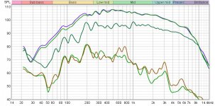
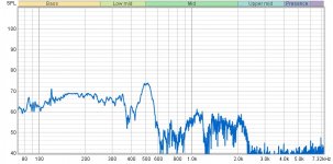
This time, everything is on one graph except for panel vs noise..
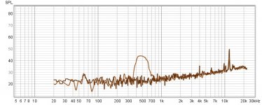
Top two traces; Driver matching at 18" measured at exact same spot in room.
Dark green; Single speaker, on axis at 50"
Brown; Panel at 50"
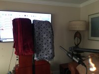
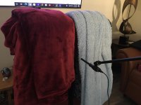
Light green; Nulling baffles on axis, where they meet, with thick blankets over both panels at 50".(picture)
It looks like the blankets are almost totally transparent and not making any difference below 250hz, so the null method looks to be accurate only above that. Does that sound correct? Good cabinet bracing will push it above that point anyway, so it may be a useful tool to analyze the audibility of well braced cabinets, of which the Dunlavy certainly isn’t.
Top two traces; Driver matching at 18" measured at exact same spot in room.
Dark green; Single speaker, on axis at 50"
Brown; Panel at 50"
Light green; Nulling baffles on axis, where they meet, with thick blankets over both panels at 50".(picture)
It looks like the blankets are almost totally transparent and not making any difference below 250hz, so the null method looks to be accurate only above that. Does that sound correct? Good cabinet bracing will push it above that point anyway, so it may be a useful tool to analyze the audibility of well braced cabinets, of which the Dunlavy certainly isn’t.
Attachments
Last edited:
Nice lamp and shade over there in the corner. A recent find, or heirloom?
I was suspecting that the blankets might prove too transparent in the bass. The only practical thing I can think of is sandbags. I have some and could make more, maybe I'll give that a try tomorrow. Thanks for all your hard work!
I was suspecting that the blankets might prove too transparent in the bass.
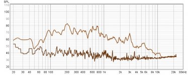
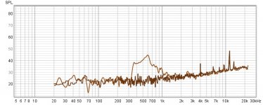
The only practical thing I can think of is sandbags. I have some and could make more, maybe I'll give that a try tomorrow. Thanks for all your hard work!Thank you! I Wanted to see if the Panel resonance could travel that far in the room, but your right, the resolution is not good, that far away. This next graph is my own speaker, but at 20"
Top traces, driver matching.
Green- Driver on axis at 20"
Brown- Panel at 20" using null method.
Top traces, driver matching.
Green- Driver on axis at 20"
Brown- Panel at 20" using null method.
Attachments
The lamp was designed by my father back in the mid 60's. Mid century modern in design. He was a pretty famous sculptor.Nice lamp and shade over there in the corner. A recent find, or heirloom?
I was suspecting that the blankets might prove too transparent in the bass.
Wow. I did the null test on my speakers with the mic situated in between, and blankets on both. This is what I got. So the bump I thought was coming off my side panel at 500hz is actually coming from a resonance in between the baffles, I'm assuming from the phase plugs interacting with each other and interfering with the null. That's the only thing I can think of. So that's a good thing, because it's not coming off my baffle. It's most likely very silent all the way across the spectrum, Just like the vibration sensor was reading. The good thing about doing lots of measurements, is that a lot of assumptions get overturned. I'm realizing just how important the vibration sensor is in addition to this. They both have limitations, but when used together, you can definitely get a more complete picture.

Attachments
Last edited:
Ah ha! Good find. I did wonder just how good a null could be achieved. This seems to show that it's better at some frequencies than others.
Thanks for the info on the lamp. Quite the heirloom, then. We had a good collection of MCM lamps before we moved twice. My father was a carver and did very sleek stylized animals in the 60s. Those we still have.
Thanks for the info on the lamp. Quite the heirloom, then. We had a good collection of MCM lamps before we moved twice.
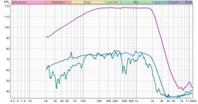
My father was a carver and did very sleek stylized animals in the 60s. Those we still have.Comparison of frequency response between vibration sensor and mic placed one mm above surface(null method) in the same exact spot on the side panel as the sensor. This is to show exactly what becomes airborne in that exact spot. Green is the mic. Mauve is driver spl at one cm that was used during testing. What to make of this? I'm not totally sure.
Attachments
Last edited:
To clarify the above graph, the vibration sensor is attached to the cabinet. I also have the 48db/octave lowpass engaged at 2khz.
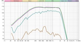
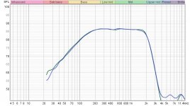
Oh yes, I forgot to include driver matching which was done this time with my solid state amp. It was the tube amp that was a little off on the previous driver matching I attempted. As you can see, the drivers are very closely matched this time around, so the test is valid down to around -25 or -30db(Per Jim's table) through most of the range, which is much better than through the tube amp.
Oh yes, I forgot to include driver matching which was done this time with my solid state amp. It was the tube amp that was a little off on the previous driver matching I attempted. As you can see, the drivers are very closely matched this time around, so the test is valid down to around -25 or -30db(Per Jim's table) through most of the range, which is much better than through the tube amp.
Attachments
Last edited:
Well I would say that the mic and the peizo basically agree, tho their frequency responses may be different. That notch around 600 could be cancellation of the out of phase drivers, or maybe cancellation of air and speaker panel being out of phase. Hard to say.
These look like useful results to me.
These look like useful results to me.
I just purchased some copper tape for shielding the piezo sensor wire. They'll also be twisted underneath. I'm going to try getting the emi as low as possible in the piezo sensor/buffer setup. The 60hz hum is pretty out of control, even with what I've already done
Last edited:
For maximum EMI suppression of low frequencies (anything under 100 kHz is low frequency to an EMI engineer), twisted pair wiring gives you the maximum benefit. A loop in the wiring is an antenna, and you want to avoid creating antennas. Twisting the wire together shrinks the loop as small as it can be.
The aluminum foil or copper tape should be grounded to the preamp chasis, and the ground lead should be as short as possible... Be aware that most of the commonly available copper tape has an adhesive which is NOT conductive, so you will need to ground to the face of the copper.
If you still have 60 Hz noise, try repositioning the power cables. Perhaps unplug anything in the room which is not needed. LED lights and fluorescent lights can be a source of noise. Halogen and incandescent don't emit much noise.
My wife says "you're welcome"...
Oh, do you have some of the discs?
Found these same ones on amazon for $7 it'll be fun to play around with them
Luvay 12Pcs Piezo Pickup Transducer Prewired - 27mm Contact Microphone Trigger - | eBay.
great deal too.
Description
Plate material: Brass
Easy to install, easy to use
Resonant frequency (kHz): 4.6 +/- 0.5 KHz
Resonant impedance (ohms): 300 max
Capacitance (nf): 20.0 +/- 30% (1 kHz)
Diameter plate: approx.2.7cm / 1.06 inch
Lead Length: approx.15cm / 5.9 inch
Color: As shown
Quantity: 12 pcs
Last edited:
For maximum EMI suppression of low frequencies (anything under 100 kHz is low frequency to an EMI engineer), twisted pair wiring gives you the maximum benefit. A loop in the wiring is an antenna, and you want to avoid creating antennas. Twisting the wire together shrinks the loop as small as it can be.
The aluminum foil or copper tape should be grounded to the preamp chasis, and the ground lead should be as short as possible... Be aware that most of the commonly available copper tape has an adhesive which is NOT conductive, so you will need to ground to the face of the copper.
If you still have 60 Hz noise, try repositioning the power cables. Perhaps unplug anything in the room which is not needed. LED lights and fluorescent lights can be a source of noise. Halogen and incandescent don't emit much noise.
My wife says "you're welcome"...
Haha! Tell her again I said thank you! So nice!
I did make sure to buy conductive adhesive copper tape, so that's covered. The recessed led ceiling lights will go off too.
Finally getting a handle on this. Apparently the DI box in bypass mode was causing the entire problem. I fixed it by taking it out of bypass mode, and then turning the effects dials down all the way, with only the level control dial turned half way up. Now the only part of the fundamental that is popping up above the now drastically lowered noise floor is the panel resonance, which is exactly as it should be. This is with the midrange driver being run without any crossover filters applied.
When I originally put this setup together, these were the result that I was envisioning.
The second graph is the opposite panel on the same speaker.
When I originally put this setup together, these were the result that I was envisioning.
The second graph is the opposite panel on the same speaker.
Attachments
Last edited:
- Home
- Loudspeakers
- Multi-Way
- Accelerometers to measure panel vibrations?