You stated some issues about boxed speakers. I replied these are no worse than those boxless speakers are blessed with. Agreed?It doesn’t really seem that there is tradeoff at all. You make the point that an OB driver could exhibit some distortion if pushed too hard, but then you state that generally isn’t the case in most listening situations. So where is the problem with OB? I don’t see one from what you have written.
Then you might exaggerate issues with boxed speakers while you could underestimate those with boxless ones like open baffle speakers.
One problems with OB’s is that cone excursions are big, even at moderate levels. Driver distortion rises with cone excursion. And it does so nonlinear fast.
One problems with OB’s is that cone excursions are big, even at moderate levels. Driver distortion rises with cone excursion. And it does so nonlinear fast.
A 12dB/oct rolloff often does not sound right, until you blend it with its conjugate. Then it disappears.Box adds box sound.
Yes because the losses at the low end can be significant, Often 10dB or more. That's a lot of extra excursion. But that's "easy" to overcome by using bigger drivers and more of them.One problems with OB’s is that cone excursions are big, even at moderate levels.
With twin 15", single 21" or dual 18" woofers excursion really wasn't a problem for me in any domestic setting. And there are some nice advantages to OB that outweigh the increased excursions.
There may be some useful info on these two website pages.
Cabinet Bracing
Cabinet Panel Vibration and Bracing
Cabinet Bracing
Cabinet Panel Vibration and Bracing
I used a phono cartridge.
How was it amplified without using a phono pre-amp with RIAA EQ?
(But the real question is not how sensitive sensors like phono cartridges or human fingers experience the vibration but can anybody hear it.)
B.
Well, yes, but I'd like something more direct. It's like when I post I want to do tone burst simulations and people answer it's just a transform of the frequency response, or the impulse, or you can just look at the group delay curve. OK yes it's all equivalent BUT not visually. In this case I hope the accelerometer will give some nice visual data of baseline and changes. OR in the spirit of true science, might show the whole accelerometer thing is hogwash.Resonances show up in the frequency response graph.
Hey there was some talk earlier about using a contact mic, instead of an accelerometer. Pano, I think noted that they don't pick up bass well. Contact mic's are piezo, so they're like capacitors. You have to run them into a very high input impedance, and then they can pick up bass just fine. I made one following the info here:
Guitar Contact Microphone Preamp : 7 Steps - Instructables
Guitar Contact Microphone Preamp : 7 Steps - Instructables
Well, what would be your measuring protocol? And what relation exists between the measured output of the accelerometer and the sound power the panel under test transmits?Well, yes, but I'd like something more direct. It's like when I post I want to do tone burst simulations and people answer it's just a transform of the frequency response, or the impulse, or you can just look at the group delay curve. OK yes it's all equivalent BUT not visually. In this case I hope the accelerometer will give some nice visual data of baseline and changes. OR in the spirit of true science, might show the whole accelerometer thing is hogwash.
If you measure a reduction in vibration, you can count that as progress. If you measure no change or just a shift in frequency (I've done that) then it's a clue to try something else. How complex does it have to be to be useful?
The problem is that you have one or a few measurements of acceleration at one or few locations on the outside of the cabinet. This small amount of information on what is going on has the potential to be as misleading as it is informative particularly for those that are not on top of the physics of what is going on.
In some ways a knuckle rap test with a constant impulse (e.g. swinging a weight on a string from a fixed height) is more reliable. This gives you the modal frequencies and possibly the damping if sufficiently resolved. You can also get an idea of the shapes of the lowest few modes by moving the mic around if you don't know them already from a simulation. From the shapes one can estimate which modes will be driven and which will not and which modes will radiate towards the listening position and which will not. It needs a bit of thought and effort but provides a fair amount of what one would like to know without any extra hardware.
An accelerometer has the potential to give us everything we want to know if you stick, measure, unstick, stick, measure, unstick,... many times over a grid on the outside of the cabinet and then use the grid and velocity measurements as input to a BEM code to give the SPL at wanted locations outside the speaker. The highest frequency resolved will depend on the grid spacing with more locations giving a higher frequency resolution. A student project with a B&O speaker is described here and there are a few others around.
Last edited:
That's about exactly what I summarized in #8. Thx for the link on the student's paper!
Even the knuckle test would have to be performed on a grid, not on one or a few spots on the panel under test. And even then: why would a transversal force represent the actual forces on the panel applied by the drivers?
Even the knuckle test would have to be performed on a grid, not on one or a few spots on the panel under test. And even then: why would a transversal force represent the actual forces on the panel applied by the drivers?


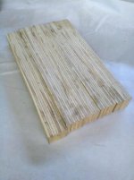
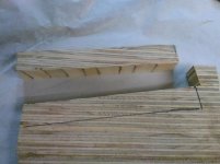
Here is just a mad idea for a ( possibly ) damped brace, I have no idea if the different layers of ply will have a damping effect, but I'll give it a try anyway. If anyone wants to measure different type of braces in a test perhaps you could give it a go, it's not much work to pva some ply together in a big block, then a day later cut it at an angle.
Great research paper, but too bad it was done using a very unconventional enclosure.A student project with a B&O speaker is described here and there are a few others around.
Even the knuckle test would have to be performed on a grid, not on one or a few spots on the panel under test.
Why? What are you going to integrate?
The knuckle rap test is a measurement of the free response of the speaker not the forced response an accelerometer would typically be used to measure.
And even then: why would a transversal force represent the actual forces on the panel applied by the drivers?
It doesn't. A free response and a forced response are not the same but they can both be viewed as different sums of the same modes. A knuckle rap test can be used to measure the modal frequencies, shapes and damping but the magnitudes for a particular forced response will be left to be estimated.
Measuring the sound radiated by a vibrating cabinet is time consuming and involves some hardware DIY speaker folk don't usually possess. Assuming an expensive scanning laser doppler vibrometer is not to hand what is usually used is a point laser doppler vibrometer which typically costs a few thousand but will be owned by most acoustical engineering institutions. Measurements would still need to be taken point by point on a grid involving a large number of locations over the surface but there is no need to stick and unstick an accelerometer and often a robot can be programmed to help automate the task.
If I wanted to measure the forced response of a DIY cabinet (which I don't because the combination of simulations plus knuckle rap tests is more informative and requires no extra hardware) I would look to borrow or rent a laser vibrometer because sticking and unsticking an accelerometer between each of perhaps a thousand measurements is not something I am prepared to do for a hobby interest. Others may see things differently.
- Home
- Loudspeakers
- Multi-Way
- Accelerometers to measure panel vibrations?