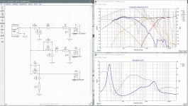
This is the result of adding a 2.2 ohm resistor in series with L1 (the mod delays were removed). To be honest, I don't really understand what I'm looking at. Are we aiming to have the phases of all drivers overlap as much as possible around the crossover frequencies?
Attachments
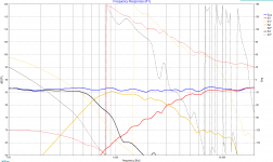
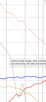
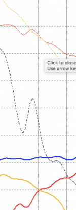
Check the attached clips for the phase behavior (dotted yellow and red lines).
Only true for the measuring plane of course. But off-axis (vertical) sims should give you a clue.
Only true for the measuring plane of course. But off-axis (vertical) sims should give you a clue.
Attachments
Last edited:
To be honest, I don't really understand what I'm looking at. Are we aiming to have the phases of all drivers overlap as much as possible around the crossover frequencies?
Pretty much. Not all the drivers though. Just the 2 drivers at each xo point for the range in which they are both contributing to the summed output.
Maybe see if crossing the mid and woofer lower might get you better phase alignment. Maybe try just a single cap on the mid as the HP filter. Maybe try 3rd order electrical on the tweeter. Or perhaps on the mid LP.
Or maybe try attaching the whole XSim file so others can play with it as well.
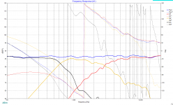
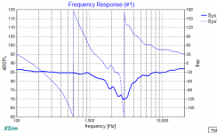
The plot with the series resistor looks better to me, but as mentioned, I don't really know what to look for. If it's just a matter of making the phase plots of mid en tweeter overlap, I'd say my initial plot on page 1 looks quite nice (shown below).
I do understand I have to take acoustic center offset into account. I'll use the formulas provided by jReave to calculate what my delays should be.
I do understand I have to take acoustic center offset into account. I'll use the formulas provided by jReave to calculate what my delays should be.
Attachments
... Or maybe try attaching the whole XSim file so others can play with it as well.
Here you go...
Edit: is this sufficient, or do you also require the FRD and ZMA files?
Attachments
Last edited:
While the fun partly is in the experiment and you could go change a crossover forever, I suggest build the speaker first, measure all response (magph) and impedance plots, be sure you do that dual channel with one reference and then start simulating for real. You don't know the acoustic centers of the drivers on the crossover frequencies until you have measured them.I'll use the formulas provided by jReave to calculate what my delays should be.
No philosophies here. Just a bit of physics. The smaller the cabinet, the less troublesome standing waves inside it (they shift upwards). No back wave if dimensions are too small eh? (What is a back wave anyway). As the highpass of the mid will work together with the electroacoustic aligning, you could even design an enclosure small enough for a true acoustic 3d order with just one cap. Just use appropriate damping inside the mid enclosure. That is why I suggested measuring CSD's and BD's.
All the sound generated by the driver when the cone is moving forward is also generated rearward when the cone is moving backwards. That's the back wave.
So what happens to it? It doesn't just disappear.
Without any internal absorption, some of it is reflected off the panel walls and passes back through the cone. Some of it is passes through the panel walls. Some of it results in internal standing waves. Some it, along with the mechanical vibrations produced by the driver, stimulate the panel resonances. Some of it, much much less than most people assume, is absorbed by the panel walls themselves.
Thus the reasons to brace and damp the panel walls and to fill the chamber with absorption material. But how much material is needed? Again I think that most people overestimate what a little bit of foam or felt or polyester can do. If the mid is working down to 300-400Hz, you are going to need inches and inches of the stuff. Better still to use a layered strategy of high density insulation for the lowest frequencies, a mid density insulation for mids and some lighter polyester stuff for the highest frequencies.
But at the same time, filling the space right behind the driver full of insulation is not a good idea. Imo. The driver still needs room to breath. It still needs some open space behind the driver.
Thus, oversize the mid chamber so you have room to apply a formidable insulation strategy but still leave uncongested room behind the driver that allows it to breath.
All of that aside, the larger sealed chamber (or even aperiodic) may also be preferred when you are using a mid that has a stiffer suspension and is happier in a vented alignment. You don't need to add an extra stiff air spring from a very small sealed box to an already stiff suspension intended for a larger vented box.
Here you go...
Edit: is this sufficient, or do you also require the FRD and ZMA files?
Nope - that's perfect.
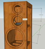
What is the distance between the tweeter and mid and between the mid and woofer? Center to center.
What is the distance between the tweeter and mid and between the mid and woofer? Center to center.
See attached, in mm. In inches this is:
Tweeter - mid: 4.7"
Mid - woofer: 7.1"
Attachments
Thanks.
Something else you need to do that will change everything is extract minimum phase from all the frd and zma files. It is the "derived" button in the "Tune" window. For the frd files, you also have to 'tail' the FR's. So choose a slope that most closely matches what the driver is already doing and choose a starting point that uses as much of the original FR as possible.
For more accuracy, you should also include the effects the boxes you've put the drivers in on both the FR and impedance. In a 3-way this can have an important effect at the resonance frequency for the woofer and/or mid. I do that in Response Modeler but you have have Excel. Otherwise I'm pretty sure VituixCAD will do that too.
I'm not saying it will be correct in the real world - I'd want to add in the box data as I said before - and measuring in box responses is really the way to go, but here's what things look like with the delays added and with minimum phase extracted from your files and with phase fairly nicely aligned at the xo regions. A couple of resonance peaks attacked on the mid and woofer as well. Definitely a 4ohm nominal speaker though.
The XSim file is attached as well.
The XSim file is attached as well.
Attachments
jReave, lots of thanks for all the help so far! Same goes for markmakk and wintermute.
I didn't quite understand all the suggestions I've had in this thread, but I'll order the drivers and assemble the speaker first. I'll get back to the finer details of XO design when I get my first measurements.
I didn't quite understand all the suggestions I've had in this thread, but I'll order the drivers and assemble the speaker first. I'll get back to the finer details of XO design when I get my first measurements.
")

On the phase matching question, what I like to see is nice close to parallel lines as close to each other as possible at the crossover point and for some distance either side. The as close to each other comment doesn't apply for your woofer crossover though since that is 3rd order acoustic. For that they should still be parallel but 90 deg apart.
Another thing you can do to check on your phase matching is reverse one of the drivers polarity and check the reverse null.
In your case, if you reversed the polarity on the mid, I would expect a null for the tweeter /mid cross point, but little to no difference for the woofer to mid cross point.
Tony.
On the phase matching question, what I like to see is nice close to parallel lines as close to each other as possible at the crossover point and for some distance either side. The as close to each other comment doesn't apply for your woofer crossover though since that is 3rd order acoustic. For that they should still be parallel but 90 deg apart.
I'll keep that in mind next time I design a crossover. I don't understand the '3rd order acoustic' part yet, how can it be 3rd order if I only use one cap and one coil?
Another thing you can do to check on your phase matching is reverse one of the drivers polarity and check the reverse null.
In your case, if you reversed the polarity on the mid, I would expect a null for the tweeter /mid cross point, but little to no difference for the woofer to mid cross point.
Your expectation is correct, that's exactly what happens.
Attachments
The rear energy is a wanted part of the fundamental resonance over its extended bandwidth, why would you want to absorb it here?If the mid is working down to 300-400Hz, you are going to need inches and inches of the stuff.
- Status
- This old topic is closed. If you want to reopen this topic, contact a moderator using the "Report Post" button.
- Home
- Loudspeakers
- Multi-Way
- Please review my design?