Hello!
I'm a beginner in building speakers, but I have studied acoustics, and I have some woodworking skills, so I decided to design and build my own speakers from scratch.
I made the drivers (woofers, mids and tweeters) myself also. They don't sound horrible, but they have quite high Qts values. LIMP measurements gave the woofer Qts of something from 1.4 to 2, and Dayton DATS V2 gave 2.1. Usually speaker drivers have Qts much lower than that, and most speaker volume calculators and design tools cannot handle a value that high. I know I could maybe make some open baffle or onken speakers, but I don't want to, because those would have to be ridiculously large.
I have read from some other threads, that there is a few tricks to deal with this situation. I tried adding some acoustically resonant material (wool) behind the cone, on the back of the driver, and it really seemed to lower the measured Qts. Other possible solution would probably be some kind of leaky enclosure.
However, the problem is that I have no idea how big should the leaky enclosure be, so that it would dampen the Q just enough. And also, how much should it leak? Should I just add some small holes, or should I make big holes and stuff them with absorption materials?
Here is some parameters of the woofer (I think the mid driver and tweeter cabinets are probably much easier to design, so I wont include their specs):
Woofer:
d = 165 mm
Qts = 2.1
Fs = 39.4 Hz
Qes = 3.0
Qms = 7.3
Vas = 33 litres
After adding few layers of thin wool on the back of the driver the Qts dropped to 1.6 and Qms dropped to 3.5. Other parameters stayed mostly the same (sadly I forgot to measure the new Vas). I believe that a good layer of mineral wool would drop them even more. However, I don't know if it can also cause some other problems, I have not found much discussion on that.
I'm planning to high pass it from 80 Hz (to leave some room for a subwoofer) and low pass it at somewhere around 800 to 1000 Hz. Hence, the resonance at 39 Hz (if it stays there with the cabinet) would not even be on its range. However, I have no idea if the high Qts (which means that the system is underdamped...?) has some effect on the sound quality on other frequencies also. In other words, should I worry about the Qts if the resonance peak will be high pass filtered anyway, or is it still important to lower it some way?
The text is long and the problem is pretty unusual, but I really appreciate if you have any suggestions or opinions about this. I have invested so much time on making the drivers, that I don't want to waste all that effort by just making some random enclosure for them and hope for the best.
Attachments
You could add an electric notch filter somewhere to compensate for the peak.
Without subwoofer, you could put them in a large closed box and combine it with an overdamped electrical high-pass to together make a Chebyshev-like alignment. Something similar is done in the QUAD ESL-63 electrostatic loudspeakers, their fundamental resonance has a Q of about 2, but it is combined with a first-order electrical high-pass response.
Without subwoofer, you could put them in a large closed box and combine it with an overdamped electrical high-pass to together make a Chebyshev-like alignment. Something similar is done in the QUAD ESL-63 electrostatic loudspeakers, their fundamental resonance has a Q of about 2, but it is combined with a first-order electrical high-pass response.
Last edited:
If you pair the combination of this driver in a large-ish box (Vb>>Vas, e.g. Vb=3*Vas) with a Linkwitz-Transform filter you can easily modify the Q of the driver-in-box combination to whatever value you want.
The driver, when in a closed box, has a second order highpass characteristic. The "Linkwitz Transform" is a biquadratic filter, so it can convert one 2nd order HP function characterized by Q1, F1 into any other 2nd order HP function characterized by Q2, F2.
Since your driver will have a high Q, the filter will just be rolling off the power exactly as it is needed to achieve the new Q (which I assume here will be lower!).
While this sounds like magic, it's not. In practice, high Q drivers have "poor" control over the cone by the motor. Another way to look at it is that the behavior at resonance is dominated by the mass+spring components of moving mass and suspension compliance and less so by the motor, otherwise Q would be lower. But even with Q=2 as long as you use a very large box so that the driver-in-box Q is not raised too much, you can still get a usable Q value of e;g. 1.0 by the LT.
Another more simplistic approach would be to try and incorporate the high Q driver-in-box into some known highpass filter function, e.g. fourth order or higher Butterworth filter. For example, a 4th order Butterworth filter combines a second order filter having Q=0.54 with another second order filter having Q=1.31. The driver-in-box can serve as one of the second order stages, e.g. the Q=1.31 one, and then you need to add a second order HP filter with Q=0.5 or so to have the combination of filter and driver-in-box take on the BUT4 characteristic. I would not be too obsessive about getting exact Q matching, but try to get close.
If you are not sure, you can just build a large box, put the driver in it, and then measure the Q using a measurement tool for speakers. Then go from there to achieve your final response by adding an appropriate filter.
Yes I'd simply cross like this, accounting for the response and see how it goes.the resonance at 39 Hz (if it stays there with the cabinet) would not even be on its range. However, I have no idea if the high Qts (which means that the system is underdamped...?) has some effect on the sound quality on other frequencies also.
I'm not certain that you can lower it further than the free air values doing it this way.Other possible solution would probably be some kind of leaky enclosure.
Thank you for your replies. I will maybe consider making some larger, floor standing enclosures with volume 3x Vas, if I cannot find a good solution for smaller cabinets. Open baffle speakers would still take too much space.
The Linkwitz-transform sounds really interesting. It could maybe correct the problems in the frequency response. But what I would like to know is, that does a high Q and poor control over the cone cause any problems that are not clearly visible on the frequency response? Can it cause a bad transient response, for example? And if so, doesn't the Linkwitz transform only correct the frequency response?
It is clearly possible to reduce the Qts with some acoustically resistant material wrapped around the back of the driver. Of course, this also adds some overrall resistance to the cone movement, which probably causes the driver to need more power for the same SPL, which causes more heating. However, If I can drop the Qts enough this way, couldn't I just reduce the box size at the same time?
Right, until Vas becomes quite large, Qts' dominates:
net volume [Vb] [L] = 20*Vas*Qts'^3.3
Qts' = Qts + any added series resistance [Rs]: HiFi Loudspeaker Design
FWIW, at a 2.0 Qts, the driver needs no box or baffle, just suspended in space since its upper mass corner is at Fs where T/S theory peters out, so with a 2.1, slightly below = 2*39/2.1 = ~37.14 Hz and will be lower still if you factor in wiring losses.
GM
CongratulationsHello!
I'm a beginner in building speakers, but I have studied acoustics, and I have some woodworking skills, so I decided to design and build my own speakers from scratch.
I made the drivers (woofers, mids and tweeters) myself also.
")
In general that points at weakish magnetic system.They don't sound horrible, but they have quite high Qts values. LIMP measurements gave the woofer Qts of something from 1.4 to 2, and Dayton DATS V2 gave 2.1. Usually speaker drivers have Qts much lower than that, and most speaker volume calculators and design tools cannot handle a value that high.
How did you magnetize tham?
That´s a huge obstacle for most DIYers.
Give this a good read.I have read from some other threads, that there is a few tricks to deal with this situation. I tried adding some acoustically resonant material (wool) behind the cone, on the back of the driver, and it really seemed to lower the measured Qts. Other possible solution would probably be some kind of leaky enclosure.
However, the problem is that I have no idea how big should the leaky enclosure be, so that it would dampen the Q just enough. And also, how much should it leak? Should I just add some small holes, or should I make big holes and stuff them with absorption materials?
Then read it again
geezerville - 1957 Aperiodic Enclosure Article
Also google and read about "variovent"
Last edited:
Hi,
before building any cabinets and designing filters, think about your drivers: a Qts such high is of course, as JM has pointed out, due to a very weak motor, which leads to bad control of the cone movements, a "sloppy" driver.
I have great respect for everyone building his or her own drivers, but here I would suggest to redesign the motor and aim for better control. FEMM is a great tool for designing motors.
All the best
Mattes
Right, until Vas becomes quite large, Qts' dominates:
net volume [Vb] [L] = 20*Vas*Qts'^3.3
Qts' = Qts + any added series resistance [Rs]: HiFi Loudspeaker Design
FWIW, at a 2.0 Qts, the driver needs no box or baffle, just suspended in space since its upper mass corner is at Fs where T/S theory peters out, so with a 2.1, slightly below = 2*39/2.1 = ~37.14 Hz and will be lower still if you factor in wiring losses.
GM
Thank you. Your answer is really informative. It makes much easier to choose the cabinet size if I end up using a lot of added resistance. But I didn't quite understand why it wouldn't need any box or baffle. Wouldn't it still form an acoustically shorted circuit near the edges of the cone?
This at resonance doesn't necessarily mean there will be a problem at other frequencies. I don't know, maybe sensitivity won't be high, if that were true it can still sound good.a very weak motor,
Thank JMFahey for posting that article, I will definately read it. That variovent also seems interesting.
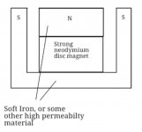
There may be something wrong with the magnet structure. I used a very strong neodymium magnet (lifts up to 40kg) with some S355 steel. S355 steel has somewhat ok magnetic properties, but it is not as good as pure iron. However, pure iron was not a good option, because nobody sells that stuff unless I order thousand tons of it. The coil is underhung, and gap is 2,5mm wide, I attached an image of it to this post. The coil has dc resistance somewhere between 4.9 and 5.4 and it's made ow 0.2mm copper wire. The magnetic gap width stays the same all the way to the bottom, but I think that's not the only problem, as my tweeter has narrower gap at the place where the coil hangs, but it has even higher Qts.
Boden:
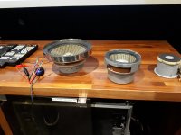
I made the cones from single layer of carbon fiber-kevlar composite. I used steel funnels as molds.
There may be something wrong with the magnet structure. I used a very strong neodymium magnet (lifts up to 40kg) with some S355 steel. S355 steel has somewhat ok magnetic properties, but it is not as good as pure iron. However, pure iron was not a good option, because nobody sells that stuff unless I order thousand tons of it. The coil is underhung, and gap is 2,5mm wide, I attached an image of it to this post. The coil has dc resistance somewhere between 4.9 and 5.4 and it's made ow 0.2mm copper wire. The magnetic gap width stays the same all the way to the bottom, but I think that's not the only problem, as my tweeter has narrower gap at the place where the coil hangs, but it has even higher Qts.
Boden:
I made the cones from single layer of carbon fiber-kevlar composite. I used steel funnels as molds.
Attachments
Well, it´s a great accomplishment making a working version.There may be something wrong with the magnet structure. I used a very strong neodymium magnet (lifts up to 40kg) with some S355 steel. S355 steel has somewhat ok magnetic properties, but it is not as good as pure iron.
Now it´s done.
Pure iron is unobtanium, but hey, you have what you have.
It was clever using a premagnetized Neo disk but it must have been H*LL assembling the magnetic circuit because they pull so strongly towards sides, (you said 40 kg
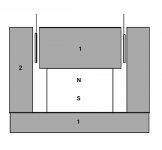
)You are losing magnet power there, typical is around 1.25mm. Again, you have what you have, not criticizing you.The coil is underhung, and gap is 2,5mm wide, I attached an image of it to this post.
The coil has dc resistance somewhere between 4.9 and 5.4 and it's made ow 0.2mm copper wire.
Curious about voice coil diameter and top plate thickness.
Amazing.Boden:
I made the cones from single layer of carbon fiber-kevlar composite. I used steel funnels as molds.
EDIT: chinese will sell you everything: frames, cones, voice coils, plates, polepieces, magnets, plus a magnetizing machine if needed, any quantity you want in multiples of 1000
Making "just one" (or a few) is a Herculean task.
Last edited:
Thank you JMFahey. Voice coil diameter is about 38mm and it has two layers of wire on it. Top plate is pretty thick, 20mm. The coil is underhung, and it has 5mm of room to move up and down. It's almost like in the attached picture, but the gap width stays the same all the way to the bottom. I don't know, maybe the saturation magnetization of the steel was still too low.
The article was somewhat useful. I will really consider making that kind of damped enclosure. However, it seemed that there was no references to any TS-parameters (maybe the article was so old). Therefore, it's still a little hard to approximate a good enclosure volume. If I understood it correctly, it doesn't even need to be very large? But the Qts of my drivers is still pretty high, so I should maybe use a good amount of damping material. Maybe some foam, wool or mineral wool? Of course I can still tweak it after making the enclosure, and that's one reason I see this as a potential enclosure type for the drivers. I also wonder if the slight loss of bass mentioned in the article could be reduced by positioning the damped vent hole somewhere else than on the front baffle.
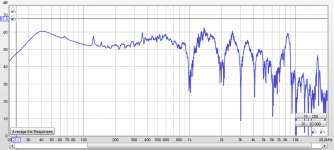
I will still attach the home-measured frequency response here. It doesn't look very good, because it's not measured in a good place with good equipment (I used a non-calibrated USB mic). However, it can still give some idea about the response. Also, when I measured with REW, some strange comb filtering appeared in the response. That does not exist in the actual fr, but it is probably caused by something in my measurement setup.
The article was somewhat useful. I will really consider making that kind of damped enclosure. However, it seemed that there was no references to any TS-parameters (maybe the article was so old). Therefore, it's still a little hard to approximate a good enclosure volume. If I understood it correctly, it doesn't even need to be very large? But the Qts of my drivers is still pretty high, so I should maybe use a good amount of damping material. Maybe some foam, wool or mineral wool? Of course I can still tweak it after making the enclosure, and that's one reason I see this as a potential enclosure type for the drivers. I also wonder if the slight loss of bass mentioned in the article could be reduced by positioning the damped vent hole somewhere else than on the front baffle.
I will still attach the home-measured frequency response here. It doesn't look very good, because it's not measured in a good place with good equipment (I used a non-calibrated USB mic). However, it can still give some idea about the response. Also, when I measured with REW, some strange comb filtering appeared in the response. That does not exist in the actual fr, but it is probably caused by something in my measurement setup.
Attachments
Before you start designing the driver, you must first decide the fundamental frequency Fd it must have. At the finished stage it will end up to be equal to Fr/Qes.
Fd = 1/(Mechanical resistance × moving mass(kg) ×2π)
Mechanical resistance = Re/(BL)²
From these parameters you can derive the efficiency.
The required Xmax determines the gap height, combined to BL determines the induction B (Tesla).
With Neodynium magnet in the pole requires a central nonmagnetic steel holding the pole piece to the back plate to provide reactive impedance, the magnet is too soft unlike Alnyco .
May be you measured wrong the Qes. Normally Fr/Qes should be above 100hz, yours is only 18hz.
Last edited:
- Status
- This old topic is closed. If you want to reopen this topic, contact a moderator using the "Report Post" button.
- Home
- Loudspeakers
- Multi-Way
- Designing cabinets for high Qts DIY drivers