Hello Everyone,
I am working on a high power LCR speaker build.
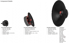
The components I have chosen are as follows:
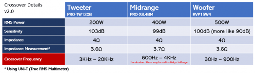
The crossover points are as follows:
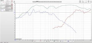
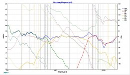
Below are the frequency response curves in REW (var smoothing):
Plus I know the woofer is really bad")
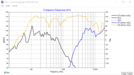
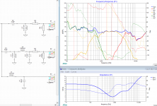
Below are the frequency response curves in XSim:
This is my first attempt at building a crossover based on measurements and I will need help. I am not taking impedance measurements for this project.
I had to manually trace the graphs using the pictures supplied in owners manual (using FPGraphTracer). Hence, before I start I wanted to check with you folks if there isn't anything crazy wrong with the frequency response graphs? I will also post the pictures next post.
Thank you in advance for your guidance and valuable feedback.
Cheers
I am working on a high power LCR speaker build.
The components I have chosen are as follows:
An externally hosted image should be here but it was not working when we last tested it.
The crossover points are as follows:
An externally hosted image should be here but it was not working when we last tested it.
Below are the frequency response curves in REW (var smoothing):
An externally hosted image should be here but it was not working when we last tested it.
Plus I know the woofer is really bad
Below are the frequency response curves in XSim:
An externally hosted image should be here but it was not working when we last tested it.
This is my first attempt at building a crossover based on measurements and I will need help. I am not taking impedance measurements for this project.
I had to manually trace the graphs using the pictures supplied in owners manual (using FPGraphTracer). Hence, before I start I wanted to check with you folks if there isn't anything crazy wrong with the frequency response graphs? I will also post the pictures next post.
Thank you in advance for your guidance and valuable feedback.
Cheers
Attachments
Last edited by a moderator:
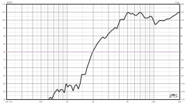
Below are the frequency graphs in the owners manual:
Tweeter
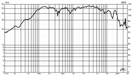
Midrange
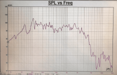
Woofer from Manufacturer
Regards
Tweeter
An externally hosted image should be here but it was not working when we last tested it.
Midrange
An externally hosted image should be here but it was not working when we last tested it.
Woofer from Manufacturer
An externally hosted image should be here but it was not working when we last tested it.
Regards
Attachments
Last edited by a moderator:
AllenB quick question the frequency graphs that are usually shown on tweeter owners manual do they account for the resistor supplied with the component or is it base fs? It does not mention anything if it is with or without.
I am sharing link to PDF manual:
WeTransfer
I am sharing link to PDF manual:
WeTransfer
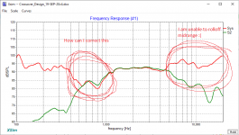
My first attempt at crossing over:
LOL I am totally unable to bring down the midrange to 4k:
This is without the system line for better clarity:
What am I doing wrong
An externally hosted image should be here but it was not working when we last tested it.
LOL I am totally unable to bring down the midrange to 4k:
An externally hosted image should be here but it was not working when we last tested it.
This is without the system line for better clarity:
An externally hosted image should be here but it was not working when we last tested it.
What am I doing wrong
Last edited:
Tweeters don't normally come with a resistor, so I wouldn't think so.do they account for the resistor supplied with the component
Your images are not linking, this is the choice of the site you are linking from.My first attempt at crossing over:
How to attach images to your posts.
Thank you I have uploaded the pictures:
Picture 1
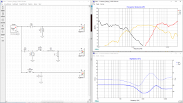
Full details; Crossover points, design components & system plot
Picture 2
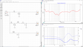
System plot only
Picture 3
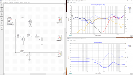
Without system plots
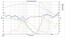
Picture 4
The problem & support needed - I have tried pretty much everything
I have uploaded the pictures:Picture 1
Full details; Crossover points, design components & system plot
Picture 2
System plot only
Picture 3
Without system plots
Picture 4
The problem & support needed - I have tried pretty much everything
Attachments
OK, first the limitations. You have not measured response phase so I asked Xsim to guess this for you. You have not measured impedance, so Xsim has supplied a simple resistive 8 ohms to work with for now.
You have not included the effect of the outside of a box, so here I'm just guessing when you see that over the hundreds of Hertz, there is a fall of a few dB. Then it flattens out for a few kHz.
I haven't looked at the tweeter yet, other than to add some resistors.
You have not included the effect of the outside of a box, so here I'm just guessing when you see that over the hundreds of Hertz, there is a fall of a few dB. Then it flattens out for a few kHz.
I haven't looked at the tweeter yet, other than to add some resistors.
Attachments
WOW that looks much better! Thank you.
Yes totally aligned to the limitations; as this is my first attempt I didn't want to go overboard.
For the tweeter the few hundred of hertz dip, I image would go up once included in box for baffle.
I will order the parts for the crossover, and start building. Should I order a few extra resistors just in case 3 - 4Ohm?
Edit: Also will reverse the polarity of midrange
Then, with a bit of fiddling you can get it looking like a place to start. When you like what you see, you can listen to it and tweak. When you come back to Xsim you can simulate the changes you've made and fix your mistakes from before.
Since your midrange seems to go so high I found it simpler and preferrable to add another capacitor, even though the result might have been usable without.
At the moment it still has a slightly low impedance around 1k, it's unclear with the current data but I'd put in a little work there.
Since your midrange seems to go so high I found it simpler and preferrable to add another capacitor, even though the result might have been usable without.
At the moment it still has a slightly low impedance around 1k, it's unclear with the current data but I'd put in a little work there.
Attachments
I'm trying to not make a big deal about the limitations so far.. but audio amplifiers don't usually like a low impedance. Best to see how low (ohms) it can go.At the moment it still has a slightly low impedance around 1k, it's unclear with the current data but I'd put in a little work there.
That's true, my amplifier can manage 4Ohm its class A/B and in the event there is a thermal overload it should go into protect.
Based on the information we have AllenB can we tell what is the nominal impedance? Seeing the simulation it seems around 5Ohm is that assessment correct?
Based on the information we have AllenB can we tell what is the nominal impedance? Seeing the simulation it seems around 5Ohm is that assessment correct?
Last edited:
- Status
- This old topic is closed. If you want to reopen this topic, contact a moderator using the "Report Post" button.
- Home
- Loudspeakers
- Multi-Way
- Need Guidance: High Power LCR Home Theatre Build (Crossover Components)