Hey Keil, yea I know only too well, life has sneaky way of getting in the way sometimes. 
Concerning the focusrite, in all likelihood it hopefully wasn't the source of the problem but what I was trying to say was that the measurements that you had done so far didn't necessarily rule it out. That's the way it appeared to me anyways.
In terms of measuring, with a USB mic you do not need the focusrite to take frequency measurements with REW. The mic goes directly into the USB port, the computer asks for the calibration file and then you are off to the races. That means there is no need for any kind of electrical timing loop. The timing of the different measurements, or in other words the location of each driver's acoustic center which determines where the signal starts in space and therefore the time it takes each signal to reach the mic, is achieved by the use of multiple driver measurements and then a little matching process in either PCD or XSim (that's what the link on finding the relative acoustic centers is all about). Now this timing information can indeed be included in the measurements but it's a little more complicated and is not something I would usually suggest for a 1st timer. Heck, the 1st method has worked so well for me that I haven't even bothered to learn how to do the other way yet.
Now with impedance measurements on the other hand, you do need to use both the output and input on the computer and most laptops these days only having the output capabilities and so it will require the use of the focusrite and the little impedance jig that I think you already made. So hopefully as I said up top, the focusrite is working fine.
Does that explain things any better?
I just looked btw - the Dayton EMM-6 is back in stock. I use the UMM-6 which is still backordered but I don't see any reason the less expensive one wouldn't work just as well.
Hope that helps.
Life sure does have a sneaky way!
Yeah the EMM is in stock, but it is a XLR mic. Thats why Im trying to look at a quicker option. But yet, I have no time frame anymore so quicker I guess really doesnt matter haha.
That is a good point about the usb mic not needing the timing loop. I did not know that. I would have thought that REW would still prompt you on needing that electrical timing loop.
So just to get this right, you plug in the usb mic and REW is all good with just that? It recognizes that it doesnt need the timing loop since the output is now on the computer and so is the input, so the timing is all done thru REW?
If so, I might as well just wait for the UMM-6! Make things easy.
And yeah I still have that jig setup for the impedance measurements. So I can for sure use the focusrite for that. I just hope I dont get those really weird readings on the tweeters as I had before ya know. Hopefully within the next couple days I can get to that, but ya never know! Haha
I guess in the meantime I can wait until it gets like steady 70° outside and then the garage will warmup enough to where I can paint these bad boys. By the time the UMM-6 is back, I should then have the speakers painted. Then its just testing and crossover time.
Thanks!
Sorry, I got confused with the EMM-6, I thought it was also a USB mic.
So a USB mic or an XLR mic for that matter - neither of them have to have any kind of special treatment that would include timing which is just another word for getting the phase right for each driver. You just take the FR measurement as you did with all the ones you have taken previously (I'm assuming there was no timing loop involved) and then you can just work out the timing issue separately by figuring out the mid and woofer acoustic centers relative to the tweeter's.
On the other hand, if you want to I think you can include timing/phase info with both an XLR or USB mic. There are some on this forum who push for this latter method, perhaps that's where your confusion is coming from but I think it's easier for a newbie to start off with simpler software (REW and XSim) and a simpler methodology.
So yes, just plug the USB mic into your computer, it should ask for the calibration file and then just hit 'Start Measuring' in REW. That's it (as long as you have REW set up correctly). Then you'll use the measurements and work out the acoustic center info and then after you've combined the FF and NF responses, you'll simply extract minimum phase and then the files are ready to go into XSim (or XSim can do the phase extraction for you too).
With the impedance measurements, consistency across the same drivers will be the 1st thing that will give us a clue about the focusrite's accuracy. Then we should take a very close look at the measured vs the spec sheets' impedance measurements. Fingers crossed that it's going to work out well this time.
I have bought the mic! It came back in stock.
But I also needed to spray paint some outside furniture here, so I have the painting station all setup. So, I'll be painting the speakers first, then put the drivers back in for testing.
Just wanted to give you an update! I hope all is well.
But I also needed to spray paint some outside furniture here, so I have the painting station all setup. So, I'll be painting the speakers first, then put the drivers back in for testing.
Just wanted to give you an update! I hope all is well.
The mic finally just came in today! Yay!
But I have recently just had a thought. What are your thoughts on adjustable rubber feet for the towers? Something like this.
I did my best when making them to make them level and flat. But my garage floor is kinda pitched. So I made it the same as the garage floor and now inside they are pretty level. But not perfect. Plus my brother has moved again and so does everyone in their life time. With that in mind, not every floor is gunna be super level all the time. So having adjustable feet would really help out with that! Though, I do not know much about how it would interfere with the sound at all. So, wondering your thoughts on this.
Thanks!
Hey!
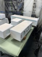
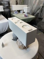
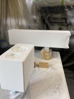
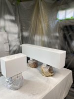
I have finally got the speakers painted and am now back into the testing phase! Within the next couple days I hope to get back to you on my results, I gotta look over everything again and make sure I am doing it right.
But here are a couple pictures from the progress!
I am excited to dive back into the final stages!
Attachments
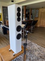
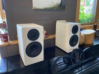
Oh very nicely done, although I have to admit that I was not expecting white.
May I suggest you start off your measuring by comparing the responses of all the same sets of drivers. By this I mean you've got 8 of the woofers, 6 of the mids and 5 of the tweeters and so you want to know if there are any differences in the responses and if so, then you'll want to try to match up any similarities/anomalies so that matching pairs of speakers will have the best pairs of matching drivers. That's if any significant differences happen to exist but let's hope they're all pretty much the same this time. Hope for the best, plan for the worst in other words.
So I would do this for both the FR and the impedance response. For the impedance you could do them all in free air but for the FR's, you'll want to make sure that the baffle diffraction effects are the same for each driver set in order to make accurate comparisons. So pick 1 of the cabinets and driver positions for each driver and then use that for all of that driver's FR measurements. Just for the purposes of driver matching, to be clear. So maybe pick the surround cabinet to measure all the tweeters and all the woofers and maybe pick a tower to measure all the mids (top or bottom driver location, doesn't matter). And I would just do farfield for all the drivers gated at 4 or 5msec or so. I'd probably cover any open driver holes on each cabinet at the same time in 1 manner or another. And be sure to label each driver beforehand to avoid any possible confusion. I just use painter's tape and a marker and slap a number onto the back of the magnets.
Post those up if there are any small differences and then we can proceed from there.
Yeah white wasn't really my choice either. Gotta satisfy the customer!
So, I get what you are saying, wanting equal set of drivers for even closer voicing throughout. Yet, I can't help but wonder how big of a different that will make since they are all the same drivers, wouldnt the difference between them be almost negligible at best? Yet, I do understand if there is a faulty driver that would be good to find out now.
My only reason for this thought is that the drivers are already all screwed in and soldered on the inside. For both the tweeters and mids I have to solder the wire on the inside face of the pin which takes just a little more patience. So, right now if I were to do your plan, that would take me a pretty long time to get through it for just a maybe, ya know? Also, this is the third time I am putting in the drivers and I have already noticed how some of the screw holes on the boxes are already wearing out and the screw just spins instead of gripping the wood tightly.
But! I do think your reasoning is valid and I have a proposition for you:
Am I able to just take the FF measurement of each driver as is and incorporate the baffle diffraction via simulation to get the final result of the FR of that particular driver. Then, if there are any significant differences, I will change them out accordingly.
How does that sound!
OK then...ah, never mind on that one. lol
What I was looking for was just small variations in response between drivers but if it's that much work then don't worry about it. Your plan is viable but even easier, let's just look at the FF for every driver and compare like to like and see how those look. The CC will obviously not have anything to compare against so depending on what the FR's look like we may want to subtract a simmed diffraction response from those ones. Or not.
Stripped wood screws is one reason I prefer machine screws and hurricane nuts (or something similar) although even those nuts can slip loose too. You might want to do a little repair on those screw holes towards the end of the project to make sure that all of them end up good and tight.
I did the FF measurements for both the rears and the towers. Also the NF of the tweeters to check that out. I have to go do some chores and other things right now. Hopefully I can get back today to do the impedance responses as well as the center measurements.
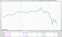
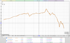
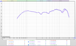
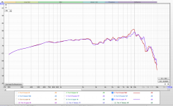
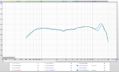
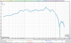
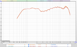
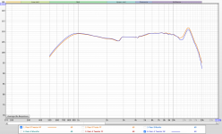
For right now tho, here are the screen captures of the FR's of each respective driver on the matching pairs of speakers. (ex. the lower woofer of Tower A with the lower woofer of Tower B)
The labels for what you are looking at are on the bottom of the screen captures. I just wanted to put these here so you can take a look if you'd like.
These are my respective lengths I measured at, according to that white paper you sent me a while back:
Towers:
- Woofers: 18" away
- Mids: 16" away
- Tweeter: 16" away
Rears:
- Woofer: 16" away
- Tweeter: 16" away
Please let me know if the lengths look good to you.
Note: The baffle step was not incorporated into these measurements, these are just the raw measurements from REW.
Attachments
-
 Screen Shot 2021-08-05 at 1.23.33 PM.png421.2 KB · Views: 104
 -
 Screen Shot 2021-08-05 at 1.23.10 PM.png414.9 KB · Views: 101
 -
 Screen Shot 2021-08-05 at 1.22.52 PM.png428.5 KB · Views: 109
 -
 Screen Shot 2021-08-05 at 1.23.45 PM.png393.8 KB · Views: 101
 -
 Screen Shot 2021-08-05 at 1.23.58 PM.png413.5 KB · Views: 98
 -
 Screen Shot 2021-08-05 at 1.24.14 PM.png358.1 KB · Views: 32
 -
 Screen Shot 2021-08-05 at 1.56.30 PM.png437.7 KB · Views: 27
 -
 Screen Shot 2021-08-05 at 1.56.44 PM.png364.7 KB · Views: 29
 -
 Screen Shot 2021-08-05 at 1.57.00 PM.png344.9 KB · Views: 27
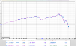
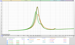
Yeah the FRs are looking nice. But I am pissed because I just did impedance tests on my tweeters and this is my result.
Fyi, all other impedance tests are looking consistent atleast. But yet AGAIN! the tweeters are just weird.
Could this possibly be due to when I solder on the wires? I know good soldering practices and am quite good at it. Yet soldering on the inside of the pin sometimes requires a little more time to make sure the wire is in the right spot, but not much more time. Do you possibly think that soldering could somehow hurt the tweeters to this extent?
Attachments
I should probably wait to see the CC driver measurements before making any suggestions but here's a couple of preliminary ones anyways:
Woofers:
- lower tower W's look good
- upper tower and rear W's look to have a similar small discrepancy
- for the towers in a 3-way where only the lower frequencies are being used, I wouldn't worry about the W differences you're seeing
- but for the rears where the xo is going to be much higher, you want a better match through the midrange if possible
- so I might try matching the tower B upper W with the rear B Woofer together for the rear woofers. Maybe see if those 2 measure any more similar below about 3kHz when they are on the same baffle. Or maybe the alternate pair, the tower A upper W and the rear A Woofer.
Both sets of mids show good similarity in the crucial midrange region.
Tweeter FR's are matching well with small differences down near resonance and up above 10kHz. Impedance measurements are a little more variable but don't freak out over them. They still look workable. This is why I wanted you to go through this little process because these kinds of small inconsistencies are not unusual. Right now you've got 2 tweeter Z's that match well, 1 that's off a little and then 1 that's fairly different (rear B). That latter one is asking right now to be used separately in the CC but again we need to see how the current CC tweeter measures too. Hopefully it will be closer to the others. Maybe you might try matching tweeters so that the small differences between pairs above about 10kHz are reduced. Again let's see what the last set of measurements show us first.
Okay thats good to hear, the tweeters being off feels like I'm back to where I was 4 months ago haha. But yeah Ill get the CC measurements today and get back to you!
For the impedance measurements I am trying to find a 0.5% tolerance 100ohm resistor. I cannot find one with 5 minutes of googling and looking around. Do you have any place you buy yours?
For the impedance measurements I am trying to find a 0.5% tolerance 100ohm resistor. I cannot find one with 5 minutes of googling and looking around. Do you have any place you buy yours?
- Home
- Loudspeakers
- Multi-Way
- First-Timer Home Theater Speaker Build