Hornresp figures
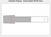
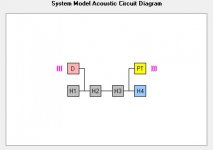
Enclosed are the Hornresp figures based on the above design and the ScanSpeak SS8531G00 driver. 2,83V, Half-space, 300 grams of Polyfill evenly filled in the first 50% of the total line.
There will be a mdf bar between the tweeter and the midbass. Also there will be four birch wood rods from front to back baffle on different heights.
Attachments
-
 Brage_Schematic.JPG17.3 KB · Views: 307
 -
 Brage_System-model.JPG16.9 KB · Views: 306
 -
 Brage_Power_Half-space_SS8531+port.JPG28.2 KB · Views: 307
 -
 Brage_Impedance.JPG24.8 KB · Views: 305
 -
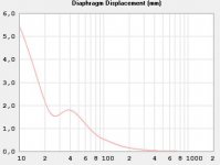 Brage_SS8531-displacement.JPG24.1 KB · Views: 299
 -
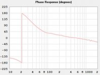 Brage_Phase.JPG25.4 KB · Views: 80
 -
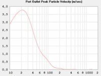 Brage_Port-velocity.JPG25.2 KB · Views: 75
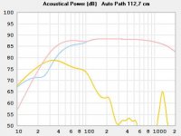
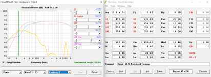
There is a slight dip at about 100 Hz but after a number of discussions on different forums I desided to go with it as is. The tradeof getting rid of it was too large for the intended and original design thoughts. This spl picture is from Hornresp whereas the same simulation in MathCad didn´t have the same dip. So regardless if it´s actually there or not the room etc will mess up the spl a lot more than this.
The main difference for the dip is to move the driver in the line, which isn´t really possible. Changing the stuffing can make the LF part to the left of the dip in the spl shart rise a little bit also changing the -f3 to some extent. But not really reducing the lowpoint of the actual dip.
The main difference for the dip is to move the driver in the line, which isn´t really possible. Changing the stuffing can make the LF part to the left of the dip in the spl shart rise a little bit also changing the -f3 to some extent. But not really reducing the lowpoint of the actual dip.
Last edited:
Bragi MLTL Restricted Terminus Speaker
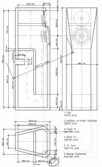
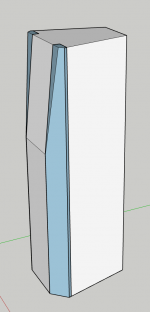
I have updated the drawing for this speaker, to include 25mm exterior panels, and 19mm internal. There are various ways to construct the front corners, that make it easier or more complicated.
The drawing shows one corner with a 45 degree chamfer, and the other with a radius. The radius (or the chamfer for that matter) could be "shaped" from a "solid" rectangular column. If a layer of 25mm and 19mm x 1 meter tall were laminated together, the inside and the outside could be shaped / carved to form a clean transition between the various panels. The trickiest would be the driver baffle that is tilted back - it could be cut as a rectangle (as opposed to a trapezoid) and have square edges.
I have updated the Hornresp, based on how I estimate it from the drawing. They were just small tweaks for the most part - except the Path got reduced quite a bit - and this actually helped raise the lower part of the response, to essentially level with the upper portion.
I am showing a 'T' shaped brace the forms a rib across the back of the driver baffle, between the drivers, and has a strut connected to the back baffle. I was assuming 25mm thick (Baltic birch) material for this.
This design has a lot going for it, I think. Non-parallel surfaces, the mass loaded transmission line with a restricted terminus; that give it a smooth response in Hornresp. The slight dip (~1 dB or so?) just above 100Hz is really the only "compromise". The amazingly low fundamental frequency of 24.6Hz with a gentle rolloff is very promising, indeed!
Attachments
Last edited:
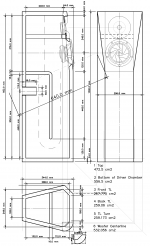
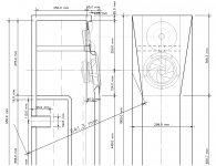
My apologies - the drawing I posted had errors in the displayed dimensions (there was a rounding factor toggled on), so here is the corrected drawing.
The diagonal dimension 641.3mm is the estimated shortest distance from the center of the woofer to the center of the restricted terminus opening. This is the easiest way to derive it from the drawing.
The diagonal dimension 641.3mm is the estimated shortest distance from the center of the woofer to the center of the restricted terminus opening. This is the easiest way to derive it from the drawing.
Attachments
Last edited:
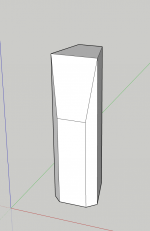
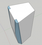
I realized that I tilted the driver baffle back too far - it is supposed to be 42mm back; but I did it 57.6mm which is right at the back corner of the chamfered corner. Which makes the number of facets - and their angles - far more complicated. I have modeled it the way I think it could be built - a 60mm x 68mm rectangular piece of solid wood, that is 1 meter tall on each corner. This allows what would be miter joints, to be instead square cuts, or nearly square cuts.
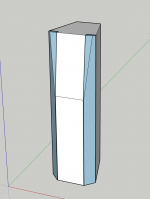
The corners can be shaped to be the clean transition between the four adjacent panels. The outside corners could be 45 degree chamfer at the bottom, or the whole thing could be radiused. The inside bottom would also need to be cut to maintain the open area the MLTL is designed to have.
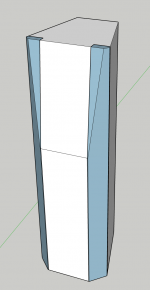
The additional piece is the inside faces of all these panels / planes have to be relatively clean. The inside top front corner, where the tilted driver baffle meets the top panel of the speaker - the inside - is where the back of the 60mm solid corner is located. On the SketchUp model, I purposely reversed the faces of the polygons, so they show as blue, so you can see the mirrored corner components.
The corners can be shaped to be the clean transition between the four adjacent panels. The outside corners could be 45 degree chamfer at the bottom, or the whole thing could be radiused. The inside bottom would also need to be cut to maintain the open area the MLTL is designed to have.
The additional piece is the inside faces of all these panels / planes have to be relatively clean. The inside top front corner, where the tilted driver baffle meets the top panel of the speaker - the inside - is where the back of the 60mm solid corner is located. On the SketchUp model, I purposely reversed the faces of the polygons, so they show as blue, so you can see the mirrored corner components.
Attachments
I have modeled the outside of the Bragi cabinet, in SketchUp. Problem is, SketchUp (which I owned back a few years ago as a standalone program) - is now an online program.
i found the new version to suck. I have an old version (that last one you could import dxf into), on an old laptop when i need it.
dave
It should actually be tilted back 40 mm. The same as length as the catheters on the outer angled front baffles. The Excel gives all the dimensions down to parts of millimetres.I realized that I tilted the driver baffle back too far - it is supposed to be 42mm back; but I did it 57......
These corner pieces will be quite complex to produce. Lots of angles to keep track of, lots of different milling etc.
Very nice looking picture though. ����
Last edited:
Okay, I'll look at things, especially the front to back dimension of the inside top panel.
I figured out why - the inside tilt IS 40mm - the inside bottom is 290mm and the inside top is 250mm. But the outside of the cabinet is 25mm farther up, and at that angle, the top of the driver baffle is an additional 2mm back.
See the attached detail drawing.
So, in this regard at least, the drawing and SU model are accurate. I looked for SU models of a woofer in their 3D Warehouse, but they don't appear to have one.
An aside - I bought a SketchUp Pro license, because I was using it to model a 5 seat electric car, I call CarBEN. I used the model to generate sections every 1" (25.4mm) and I used those to cut out foam on a CNC machine; which I assembled into a full size prototype. My intention is still to fiberglass the car, and take it to a wind tunnel, to see if it is a low drag as I hope. Here's my blog post of the construction process of CarBEN: Neil Blanchard Designs: CarBEN EV5 Construction
Attachments
Last edited:
An aside - I bought a SketchUp Pro license, because I was using it to model a 5 seat electric car, I call CarBEN. I used the model to generate sections every 1" (25.4mm) and I used those to cut out foam on a CNC machine; which I assembled into a full size prototype. My intention is still to fiberglass the car, and take it to a wind tunnel, to see if it is a low drag as I hope. Here's my blog post of the construction process of CarBEN: Neil Blanchard Designs: CarBEN EV5 Construction
Interesting project 😉
Yes, everything is INSIDE. As the upper front baffle is tilted the 25 mm board actually measures a little bit more than 25 mm in the HORIZONTAL plane due to the tilt. So remember to keep every measure intact from the inside. The outside will be whatever it will be.
Understood - on the SU model, I was working on the outside, so that's how I was referring to the tilt. Different aspects of the same thing.
Interesting project ��
Thanks!
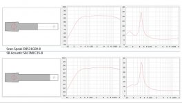
Two different drivers in the exact same cabinet. Both drivers are very much appreciated in both DIY and commercial speakers. This cater for an intersting situation where one can build the same design in two diferent price ranges.
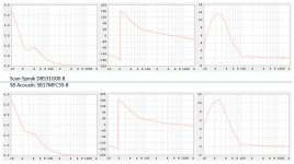
The drivers SB Accoustic 17MFC35-8 and Scan-Speak D8531G00-8.
The SB version is quite sensitive for the filling so it´s possible to trade impedance etc versus a higher spl at the LF end, and vise versa just with more or less filling.
The drivers SB Accoustic 17MFC35-8 and Scan-Speak D8531G00-8.
The SB version is quite sensitive for the filling so it´s possible to trade impedance etc versus a higher spl at the LF end, and vise versa just with more or less filling.
Attachments
- Status
- This old topic is closed. If you want to reopen this topic, contact a moderator using the "Report Post" button.
- Home
- Loudspeakers
- Multi-Way
- Bragi - 2 way Mass loaded Transmission line for Scan Speak drivers and wave guide