Here's the gif, the difference plot was not a simple solution so far so that may not happen. You can see the changes clearly when you look. The peak of the SPL is shifted, the first two contours cross over each other more often and the further off axis vertically the more ripple there is in the response tending towards slight nulls at some frequencies.
Attachments
Dave Zan posed some questions...to reduce centre to centre distance and what effect that would have.
It turned out to be much more complicated...")
I kind of expected it would be more complicated than expected, first law of software.
So thanks once more for the effort, obviously not just for my benefit but for everyone to learn more.
It is an eye opener to see the disturbance to the WG response from the woofer alone, even when not nested in the WG.
The incremental difference from the nested closer distance seems rather small.
Here's the gif, the difference plot was not a simple solution so far so that may not happen. You can see the changes clearly when you look.
Unfortunately the vertical scales don't quite match to overlay, so it's difficult to compare exactly.
Is there an easy way to make it switch from one view to the other on demand rather than have it jump interminably?
A difference plot would be very helpful.
The real key, as has already been noted, will be to compare the "whole catastrophe" with both the WG and woofer driven, around crossover frequencies, to see if the reduced C to C distance interaction makes up for the likely incremental extra disturbance in the WG response.
I expect that will be more complicated than expected too.
Maybe we can collaborate a bit, where are you in Oz?
Best wishes
David
Last edited:
It ended up being more a CAD task than anything else to allow the meshes to be generated properly. I'm glad you and others found the effort worthwhile.I kind of expected it would be more complicated than expected, first law of software.
So thanks once more for the effort, obviously not just for my benefit but for everyone to learn more.
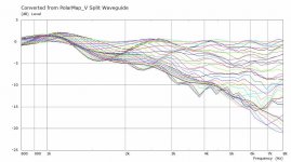
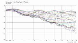
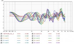
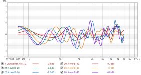
Yes the woofer is the main culprit but I think the scaled graphs I'm adding below show the differences more clearly and that there's an overall shift to the diffraction pattern that is not positive from the split.It is an eye opener to see the disturbance to the WG response from the woofer alone, even when not nested in the WG.
The incremental difference from the nested closer distance seems rather small.
I have slowed down the gif as much as I can due to the forums file size limits for gif's. I have added the graphs as separate images so you can switch at your leisure in the same postIs there an easy way to make it switch from one view to the other on demand rather than have it jump interminably?
A difference plot would be very helpful.
Having seen the damage caused by the woofer I am actually more interested to see if there is way to reduce that with the use of a freestanding guide in the first instance. Now I've got the scripts sorted I'm more willing to let the sims run for longer on bigger devices, overnight if necessary.The real key, as has already been noted, will be to compare the "whole catastrophe" with both the WG and woofer driven, around crossover frequencies, to see if the reduced C to C distance interaction makes up for the likely incremental extra disturbance in the WG response.
I expect that will be more complicated than expected too.
Collaboration is always welcome, I'm on the Gold Coast which currently seems much further way from NSW that it did beforeMaybe we can collaborate a bit, where are you in Oz?
Scaled normalized polar curves added as wesayso suggested. They get messy but the pattern shift is clear.
Attachments
-
 Waveguide+Woofer Split IB V Norm Curves.jpg68.6 KB · Views: 68
 -
 Waveguide+Woofer IB V Norm Curves.jpg66.9 KB · Views: 67
 -
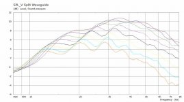 Waveguide+Woofer Split IB V SPL Scaled.jpg50.5 KB · Views: 77
 -
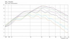 Waveguide+Woofer IB V SPL Scaled.jpg50.2 KB · Views: 344
 -
 Split Scaled Polar Curves.gif341.5 KB · Views: 332
 -
 Split Scaled.gif255.7 KB · Views: 347
...you and others found the effort worthwhile.
Hopefully you too. I usually find my answers to questions help me understand better at least as much as the questioner.
... so you can switch at your leisure in the same post
Thanks, that's much better.
What would be nice is a plot of the difference between the two cases.
...I am actually more interested to see if there is way to reduce that ...in the first instance.
How would this work?
Presumably you still need a woofer.
Other than the Multi Entry Horn option how would the woofer fit with a freestand horn?
I'm on the Gold Coast which currently seems much further way from NSW that it did before
Yeah, a bit far to drive over for a brainstorm or code session.
What with bushfires and then Covid I haven't even made it to William Cowan's (CowanAudio) place and it's only 20 km.
If I make it to the ' Coast or you visit Canberra I will definitely shout a round of drinks
Best wishes
David
Very true and in this case produced an unexpected result that now needs further investigation.Hopefully you too. I usually find my answers to questions help me understand better at least as much as the questioner.
So far this is the best I can do. The plain woofer measurement divided by the split waveguide measurement after normalization of the polar curves. These are the negative vertical angles in 10 degree increments. I could not find a simple automated way to do this so experimenting is quite tedious.Thanks, that's much better.
What would be nice is a plot of the difference between the two cases.
Reduced angles and a better legend
To see if the improved termination from the freestanding guide reduces the interference effects in a meaningful way. There will inherently be a bigger gap too.How would this work?
Presumably you still need a woofer.
Other than the Multi Entry Horn option how would the woofer fit with a freestand horn?
Maybe one dayYeah, a bit far to drive over for a brainstorm or code session.
What with bushfires and then Covid I haven't even made it to William Cowan's (CowanAudio) place and it's only 20 km.
If I make it to the ' Coast or you visit Canberra I will definitely shout a round of drinks
Best wishes
David
In the mean time if you have any follow up thoughts or ideas throw them in here.Attachments
... To see if the improved termination...reduces the interference effects...
Of course we can have a free-stand horn and put the woofer far away to reduce interference.
But that will ruin the vertical polars.
My first intuition is that the ripples from the close woofer are a few dB whereas the nulls from interference between two sources near crossover can be arbitrarily deep.
Also the ripples can be mostly equalised, I suspect, but the nulls are not minimum phase and therefore can't be effectively equalised.
So I am inclined to try to minimise the C to C distance even at the cost of a little ripple.
The Harman/Toole "spinorama" research would be a sensible start to look at the trade-offs.
You probably know that they have a "preference score" that combines on and off axis response, especially flatness, to produce an overall metric.
(The current published Spinorama standard (CEA2034) has a few errors but the corrections were worked out over at AudioScienceResearch)
The Unity/MEH implementation certainly solves this problem in a neat way but I am not sure whether it creates more other problems than it's worth.
Genelec have some monitors where paired woofers are behind the baffle and load into slots that exit near the horn but with minimal disturbance to the contour.
The woofers are also not round, presumably to help place them close vertically.
Measured response is pretty nice.
If you have an idea how to combine a free-stand horn with a reasonable C to C woofer then I would love to see a sketch.
Best wishes
David
Last edited:
I think it might be profitable to use abec to examine whether unity/meh does indeed cause problems. I can see the reluctance to degrade the amazingly good polars of an ATH horn but the damage to polars near XO due to CTC could well be worse. If designing for home environment at reasonable SPLs e.g. 105 db peak rather than 130 db, the midrange taps can be fairly small if designing for 100 Hz ++ and separate subs.
Its no doubt easier said than done to model the taps in ABEC. At first blush they are "just" holes. David McBean's analysis was that they were helmholtz resonators.
Its no doubt easier said than done to model the taps in ABEC. At first blush they are "just" holes. David McBean's analysis was that they were helmholtz resonators.
True, and there shouldn't be need for four midrange speakers and two low mid speakers, maybe even one mid speaker is enough for home use. If it is a kickass 1.4" compression driver a single 6" or 8" mid driver might be enough to take to 100hz while still making it to the crossover shy of 1khz? Or, it might turn out that small hole very close to throat affects less so smaller mid driver would be better with 1" throat driver. At least I think it would affect higher frequencies only while a bigger hole further in the throat would show up diffraction lower in frequency. Oh boy, a ATH optimized mouth MEH could be the holy grail!
Effect of the taps is very difficult to measure so I think simulation is the only way to find out.
ps. measurement could be done with a waveguide before making the tap(s) and then with the tap(s) made and compare.
Moreover, a proper mouth termination would be and upgrade to any present MEH out there
Last edited:
Sorry for the long split post but it seems the best way to respond to the different points made
Far away wasn't my intention but it will be interesting to see how far it needs to be to reduce the interaction or if the rollover termination is beneficial enough to consider losing 50mm or so of CTC distance on a 15" driver.
This entire project is designed to see if their research works for me
Yes I am familiar with the ASR threads and Olive's preference score. At this point I see two good options Geddes ish flat DI and some ripple with a down sloping on axis, or gently rising DI and flat axial and smooth off axis.
I would like to try both if it becomes a practical reality.
The Genelec coaxial and slot are a neat solution for sure. I'm not sure how well that can be translated to bigger drivers. An array of smaller drivers through slots could well be a good alternative. I really must build with what I have already before planning the next iteration this time
Yes it is not at all easy to model the taps with a BEM mesh. It becomes a CAD and mesh problem to generate anything usable high resolution would be needed. ABEC can use lumped elements too but the results would be very simialr to hornresp and wouldn't really explore the polar degradation as well.
By exploiting quarter symmetry in ABEC the simulation time might be brought under control enough to make it worth a try. Depends how much wet weather time I get to fill with this sort of stuff.
Of course we can have a free-stand horn and put the woofer far away to reduce interference.
But that will ruin the vertical polars.
Far away wasn't my intention but it will be interesting to see how far it needs to be to reduce the interaction or if the rollover termination is beneficial enough to consider losing 50mm or so of CTC distance on a 15" driver.
Yes and a similar thing is seen in splitting the waveguide too there are some features that will remain off axis and in the combined response. Without an accurate compression driver lumped model taking combined sims further doesn't seem the best use of time and resources.My first intuition is that the ripples from the close woofer are a few dB whereas the nulls from interference between two sources near crossover can be arbitrarily deep.
The ripple can be equalised successfully if it is consistent with angle if it isn't then a choice would have to be made between on and off axis.Also the ripples can be mostly equalised, I suspect, but the nulls are not minimum phase and therefore can't be effectively equalised.
So I am inclined to try to minimise the C to C distance even at the cost of a little ripple.
The Harman/Toole "spinorama" research would be a sensible start to look at the trade-offs.
You probably know that they have a "preference score" that combines on and off axis response, especially flatness, to produce an overall metric.
(The current published Spinorama standard (CEA2034) has a few errors but the corrections were worked out over at AudioScienceResearch)
This entire project is designed to see if their research works for me
Yes I am familiar with the ASR threads and Olive's preference score. At this point I see two good options Geddes ish flat DI and some ripple with a down sloping on axis, or gently rising DI and flat axial and smooth off axis.
I would like to try both if it becomes a practical reality.
The current simulations have made me think that smaller holes in the waveguide further out may actually be less of a detriment to polar performance than a woofer placed below.The Unity/MEH implementation certainly solves this problem in a neat way but I am not sure whether it creates more other problems than it's worth.
Genelec have some monitors where paired woofers are behind the baffle and load into slots that exit near the horn but with minimal disturbance to the contour.
The woofers are also not round, presumably to help place them close vertically.
The Genelec coaxial and slot are a neat solution for sure. I'm not sure how well that can be translated to bigger drivers. An array of smaller drivers through slots could well be a good alternative. I really must build with what I have already before planning the next iteration this time
You'll be able to see a 3D model if I can get it to work.If you have an idea how to combine a free-stand horn with a reasonable C to C woofer then I would love to see a sketch.
Yes similar to what I said above, I would be using the 1.4" drivers I have and trying to target as low a crossover as possible to the woofers to avoid midrange taps. That seems to be working in mark100's synergies.I think it might be profitable to use abec to examine whether unity/meh does indeed cause problems. I can see the reluctance to degrade the amazingly good polars of an ATH horn but the damage to polars near XO due to CTC could well be worse.
Its no doubt easier said than done to model the taps in ABEC. At first blush they are "just" holes. David McBean's analysis was that they were helmholtz resonators.
Yes it is not at all easy to model the taps with a BEM mesh. It becomes a CAD and mesh problem to generate anything usable high resolution would be needed. ABEC can use lumped elements too but the results would be very simialr to hornresp and wouldn't really explore the polar degradation as well.
It could well be but it is a very difficult design and fabrication project. The reason why it does not exist alreadyOh boy, a ATH optimized mouth MEH could be the holy grail!
Effect of the taps is very difficult to measure so I think simulation is the only way to find out.
Moreover, a proper mouth termination would be and upgrade to any present MEH out there
By exploiting quarter symmetry in ABEC the simulation time might be brought under control enough to make it worth a try. Depends how much wet weather time I get to fill with this sort of stuff.
...
It could well be but it is a very difficult design and fabrication project. The reason why it does not exist already
By exploiting quarter symmetry in ABEC the simulation time might be brought under control enough to make it worth a try. Depends how much wet weather time I get to fill with this sort of stuff.
Very true, a trade off, but hey, people are getting to other planets soon, there is no task too big trying to get to the HiFi heaven
Anyway, I've thought that the bwaslo style DIY MEH which is the easiest one to tackle could be built with better mouth with similar effort, only need to simulate how to bend the panels (kerf bending) to get better mouth termination. Won't be perfect, but the easiest to build and should be better than what this type MEH have had (or DSL synergies have . I wish I had more time to this, to learn the CAD and ABEC....can be made somewhat smaller compared to a typical "boxed" one. Think about that
If a rolled back termination, possibly over only part of the circumference, can help then I am all in favour.
A beautifully smooth horn is a fine achievement but it would be a pity if the crossover to the woofer then puts deep cancellation nulls into the response.
So how would you combine the woofer and free stand horn?
Best wishes
David
You mean cancellation nulls somwhere in the vertical plane? That can't be completely avoided in that kind of design but I believe that with a careful crossover work they can be made benign to overall sound. They can be narrow and have absolutely no effect on power response, for example.
I would made the raw woofer free standing as well, as close to the WG as possible. That's what I want to do, i.e. some kind of "open baffle", even though there won't be a baffle at all. There shouldn't be much reflection off the WG body because the front-back cancelation in that direction. Well, at least that's the theory. Pet007 measured a free standing waveguide placed on a woofer box and there was no noticeable degradation - that keeps the hope.
One should take note how quickly the sound intensity drops around the free standing waveguide. That's the nice feature.
Coaxialy mount the woofer behind the compression driver and use expanding taps from the woofers phase plug (that contains the compression driver) into the main horn bell. A bit like the RH co-entrant horn: Renkus Heinz 1996 unity horn patent? US5526456A
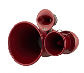
would look a bit like a Void airmotion but with only the large horn and additional side horn ducts:
https://voidacoustics.com/support/air-motion/Air_Motion_Specification_Sheet_V1.1.pdf
(and would hopefully have much better directivity plots than said speaker!)
would look a bit like a Void airmotion but with only the large horn and additional side horn ducts:
https://voidacoustics.com/support/air-motion/Air_Motion_Specification_Sheet_V1.1.pdf
(and would hopefully have much better directivity plots than said speaker!)
You mean cancellation nulls som[e]where in the vertical plane?
Yes (if we assume the woofer under or over the horn, of course.)
...but I believe that with a careful crossover work
Yes, how that crossover should work is precisely my concern.
Careful crossover work can't compensate for physical separation except to re-aim the nulls.
Since the response varies with direction it can't be equalised effectively.
So I don't see exactly of what we need to take care?
...They can be narrow and have absolutely no effect on power response, for example.
They won't effect the power response but they will mess up the early reflections response.
The research indicates that this early reflection response is important.
Flat power response doesn't prove much by itself, a speaker could hypothetically aim hi frequency to the floor to equalise power response but still sound bad.
So power response is not a sufficient condition.
Best wishes
David
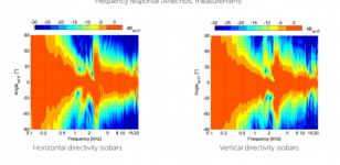
would look a bit like a Void airmotion...
(and would hopefully have much better directivity plots than said speaker!)
The "pile of independent horns" has always looked to me like it would have polars that were also a pile...
of ****.
The Void polars confirmed my expectations!
Hence my scepticism of proposals for a free stand horn.
But not to rubbish your RH proposal because maybe there's a way that I haven't seen yet, hence my interest too.
Best wishes
David
Attachments
What about aiming the null(s) in other directions than those corresponding to the first floor/ceiling reflections? That would be the careful crossover work.
I think what one should do is aim a null at the floor at the angle at which its null reflection hits the listener in the face. If you can do that and keep the main beam on the same spot, then you have a winner. A lot of variables go into that, including listening distance.
I would much rather have a unity/MEH horn and not have to juggle those variables or constrain my listening position. Given your optimal/near optimal horn shapes, it would seem reasonable to 3D print adapters for mounting several ~5" drivers on the back side of the horn at the distance appropriate for 500 Hz XO and playing them bandpass through (small) drilled holes.
- Home
- Loudspeakers
- Multi-Way
- 2 way waveguide speaker build ABEC modelling