OK let's try a concrete example. Consider someone that wants to use BEM to simulate a tweeter and waveguide to match some of the measurements in the augerpro "Open source Waveguides for CNC & 3D printing!" thread. Between 10-20kHz these tend to have pretty significant bumps and dips due to the wavelength approaching the same size as the physical bumps and dips of the tweeter and throat. What resolution do you think would be required to accurately reproduce those bumps and dips using ABEC?You seem to completely ignore the nature of the problem here. We are not talking in general, we are talking about waveguides in baffles, driven by small apertures at the throats.
There is of course a fair chance this has already done for some combinations of tweeter and waveguide so if anyone is aware of an example or two please post a link.
All I can say is that I've made probably hundreds of simulations
... out of which you built and verified IRL?
//
We already saw several examples in this thread, there's no need to change the subject to something different. Due to the fact that the details of the actual wavefronts at the exits of compression drivers are still unavailable, the simulations at question are seldom done much above 10 kHz, the less to 20 kHz, as you may have noticed. What's being used instead is a perfectly uniform wavefront at the throat. Still, there's much to see below 10 kHz - almost all the important, I'd contend.
How closely these simulations match the reality with real-world driver was never a question (and there's quite a good match, as has been shown in some other threads). The issue brought here was a "grid independence" which has nothing to do with it.
How closely these simulations match the reality with real-world driver was never a question (and there's quite a good match, as has been shown in some other threads). The issue brought here was a "grid independence" which has nothing to do with it.
Last edited:
The two are not mutually exclusive, you can be both rude and correct all at the same time. Just because something is factually correct in general does not make it any less insulting when directed at an individual.If you feel a statement of fact is a put down then it is perhaps best l refrain from posting further in your thread. It may be for the best since last time I helped someone on this forum perform a grid independence study they got a bit irritated by the required effort and care which is why I didn't explain directly.
I have no wish for you to stop posting (as you clearly have knowledge pertaining to the task at hand), only to think about how your comments might be received. I will assume for now it was not your intention to insult and we can move on.
Let's be clear that ABEC is commercial code designed for modelling of speakers and rooms. I have the commercial version as Joerg Panzer was kind enough to give me a student licence. It is just the same as the demo version in functionality apart from the ability to save, which is very helpful.The rule of thumb widely used by engineers is "6 elements per wavelength". ... The OP is using coarser grids than this despite using the least accurate element (flat constant triangle) which almost certainly wouldn't be optimal for his case if there was an option to use higher order elements typically present in larger industrial codes.
I am not aware of any accessible industrial code fit for this purpose which would be any more accurate or useful in simulating loudspeakers. If you are or have some examples to share then please do so.
6 elements per wavelength for 12KHz would be an element size of 4.76mm. I am using a 5mm element size at the driver and where the important curvature of the horn unfolds. This then transitions to 10mm further out and the cabinet behind is much coarser because it's effect is much less.
Using a 4mm element size throughout would increase the computational time quite considerably so I usually don't do that on large items because of the element count.
Like mabat I have tried using higher density meshes because when I started I simply assumed that the higher the resolution the better. What I found was that it made very little difference to the overall trend but made the solve time impractical for me.
I didn't need the clarification as I have followed mabat's progress and already found the same conclusion myself.Thanks for the clarification which should help the OP and others determine the basis for the confidence.
My aim has been to reduce the numerical inconsistencies and spikes that are signs that something has gone wrong in the simulation. I am satisfied with the level of accuracy for the amount of cpu time needed. The proof will be when I build it and measure to see how close the prediction was to reality. As long as I can get the CNC to co-operate that will happen.
I am not simulating the internal parts of a jet engine here just a waveguide in a baffle. The worst thing that will happen is I will waste a sheet of mdf on the baffle.
OK let's try a concrete example. Consider someone that wants to use BEM to simulate a tweeter and waveguide to match some of the measurements in the augerpro "Open source Waveguides for CNC & 3D printing!" thread. Between 10-20kHz these tend to have pretty significant bumps and dips due to the wavelength approaching the same size as the physical bumps and dips of the tweeter and throat. What resolution do you think would be required to accurately reproduce those bumps and dips using ABEC?
There is of course a fair chance this has already done for some combinations of tweeter and waveguide so if anyone is aware of an example or two please post a link.
Gaga simulated some of them for him in ABEC which were included in that same thread. On a six inch waveguide for a tweeter the resolution could be much higher for the same solve time due to the physical size difference.
It seems to be accepted by most that simulations much above 10KHz should not be relied on for any level of accuracy as the potential for errors that will significantly affect the outcome are much higher.
But it isn't the mesh density that limits the accuracy here (maybe it still could be improved slightly by changing the element size more gradually to the back). Mainly it is the deviation of the assumptions made about the source wavefront from the real-world device. That's not so easy to overcome but I still hope that measurement of the exit wavefront will be possible and that it will be possible to incorporate it into these simulations.... I am not simulating the internal parts of a jet engine here just a waveguide in a baffle. The worst thing that will happen is I will waste a sheet of mdf on the baffle.
I was trying to say the same above perhaps it didn't come across well. When you get to automating the enclosure script I'm sure you will be able to have a gradual transition like you do on the waveguide. A similar thing could be done manually but it would be a fair amount of effort.
Sure, with Gmsh API it means just setting the numbers to whatever you want.
- It seems that at least three of us are going to make measuremets of the actual waveguides like the one you show (all quite similiar in fact) in the near future. That will be another interesting moment and I'm really looking forward to that. I believe no one will be disappointed.
- It seems that at least three of us are going to make measuremets of the actual waveguides like the one you show (all quite similiar in fact) in the near future. That will be another interesting moment and I'm really looking forward to that. I believe no one will be disappointed.
Last edited:
We already saw several examples in this thread, there's no need to change the subject to something different. Due to the fact that the details of the actual wavefronts at the exits of compression drivers are still unavailable, the simulations at question are seldom done much above 10 kHz, the less to 20 kHz, as you may have noticed. What's being used instead is a perfectly uniform wavefront at the throat. Still, there's much to see below 10 kHz - almost all the important, I'd contend.
How closely these simulations match the reality with real-world driver was never a question (and there's quite a good match, as has been shown in some other threads). The issue brought here was a "grid independence" which has nothing to do with it.
OK!
//
I am not aware of any accessible industrial code fit for this purpose which would be any more accurate or useful in simulating loudspeakers. If you are or have some examples to share then please do so.
Like all software Akabak (it doesn't seem to be called ABEC anymore on the website) has pros and cons when it comes to simulating loudspeakers. The pros mainly seem to revolve around using the software as a standalone program on Windows for speaker simulations with the lumped model for the motor, a model for an infinite baffle, etc...
Some of the cons for a speaker company might be:
- it runs on Windows rather than linux which is the most common platform for large simulation programs requiring multiple processors
- it is not designed to integrate with the typical workflow of an engineering company by interfacing as seemlessly as possible with the particular CAD, FE models, plotting, scripting software used by the company.
- it lacks higher order elements to reduce the computational costs of the simulation for a given level of accuracy.
- it lacks techniques like the fast multipole method which can raise the computational efficiency at the price of a small-to-negligible loss in accuracy if wisely introduced
- it cannot be coupled with structural FE simulations
I am not overly familiar with what is used by home audio companies having more knowledge of the "jet engine" type industry and the numerical methods themselves but I have seen some of the speaker companies here in the UK like KEF, Celestion, B&W mention PAFEC when BEM has popped up in their marketing bumpf. The main suppliers of large engineering simulation software (COMSOL, ANSYS, Siemens, etc...) have BEM that can be coupled to FEM and it tends to be provided as a module of the full simulation package rather than a standalone program.
My aim has been to reduce the numerical inconsistencies and spikes that are signs that something has gone wrong in the simulation. I am satisfied with the level of accuracy for the amount of cpu time needed. The proof will be when I build it and measure to see how close the prediction was to reality.
At the risk of overly repeating myself, what you have described is seeking a solution that is consistent (i.e. a valid approximation of the governing equations subject to the imposed boundary conditions) but where the level of numerical accuracy is unknown and to be estimated at some time in the future.
Gaga simulated some of them for him in ABEC which were included in that same thread. On a six inch waveguide for a tweeter the resolution could be much higher for the same solve time due to the physical size difference.
Thanks. I have looked at some of his posts and he is indeed using a 3D code to understand and assess the 3D physics of a tweeter+waveguide along the lines I suggested above. Good stuff although I didn't come across a direct attempt to determine required resolution for numerical accuracy but may have missed it.
It seems to be accepted by most that simulations much above 10KHz should not be relied on for any level of accuracy as the potential for errors that will significantly affect the outcome are much higher.
The frequency upto which the solution remains accurately resolved depends on the grid resolution and the accuracy of the elements. If you want to resolve upto 20kHz rather than 10kHz it simply requires using smaller and/or higher order elements. One can modify this requirement a bit by not having any gradients in the solution to resolve but this rather defeats the purpose of using a 3D code. A lower dimensional approach more like hornresp would seem a more efficient tool in these circumstances. One can also get tripped up by using flat elements on curved surfaces even without gradients in the solution field.
If this is what you mean by that -andy19191 said:... I didn't come across a direct attempt to determine required resolution for numerical accuracy
... achieving "grid independent" solutions in 3D. That is, ones where refining the grid significantly (i.e. halving element dimensions) doesn't change the predicted solution significantly.
then we have done exactly that, as we told you already at least three times.
What I have is ABEC, the name has been changed to AKaBak in the latest iteration and all references to ABEC have been removed. The underlying modelling is the same but the interface has been moved to a full GUI input type perhaps to resemble COMSOL. As ABEC was free for me to use non-commercially I don't see any of the others you mentioned competing on priceLike all software Akabak (it doesn't seem to be called ABEC anymore on the website)
")
I agree with the first part but less with the second. The accuracy of any of my simulations has yet to be determined, but other very similar simulations using the same tools have been verified with actual measurements and the accuracy was quite good. If this is not helping you to understand where I am coming from then lets agree to disagree on this point.At the risk of overly repeating myself, what you have described is seeking a solution that is consistent (i.e. a valid approximation of the governing equations subject to the imposed boundary conditions) but where the level of numerical accuracy is unknown and to be estimated at some time in the future.
I don't remember exactly but I suspect he used a similar method to what's been described here. Checking the mesh files to determine if the mesh is fine enough to reasonably describe the features that are attempting to be modelled. Checking the result and refining again if necessary.Good stuff although I didn't come across a direct attempt to determine required resolution for numerical accuracy but may have missed it.
I don't really agree with this entirely for the reasons I and mabat stated before. Yes to go higher more resolution is needed in general but it is not the resolution that is the confounding problem. It is the breakdown in the assumptions being used that cause the simulation to be unreliable at very high frequencies. Non pistonic movement, breakup, thermal effects, bending modes. All of the things that call for an FEA / FEM approach.The frequency upto which the solution remains accurately resolved depends on the grid resolution and the accuracy of the elements. If you want to resolve upto 20kHz rather than 10kHz it simply requires using smaller and/or higher order elements. One can modify this requirement a bit by not having any gradients in the solution to resolve but this rather defeats the purpose of using a 3D code. A lower dimensional approach more like hornresp would seem a more efficient tool in these circumstances. One can also get tripped up by using flat elements on curved surfaces even without gradients in the solution field.
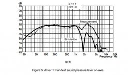
Modelling a compression driver up to 10K works well enough with just a flat disc at constant acceleration or velocity. A dome is more problematic and would likely require more effort and testing to verify the basic accuracy.
If this proves to be a success I will move on to domes to see what can be done there.
If this is not helping you to understand where I am coming from then lets agree to disagree on this point.
There is nothing to disagree about since understanding where you and to some extent mabat are coming from was my main interest in posting. As I mentioned earlier I have previously provided guidance here on how an experienced engineer would set about estimating accuracy and establishing a numerical solver is behaving as it should. If I recall correctly it was FEM rather than BEM but the differences in approach are minor. Had you expressed an interest when prodded I would have done likewise here.
Although the poster accepted the guidance and performed the study the information gathered was clearly of low value to him. The responses in this thread have to some extent helped clarify why since I rather suspect you look at and value the information in simulations in a fairly similar way to the earlier poster and rather differently to myself. There's nothing wrong with this in itself only a difference in the reliability of the information that can be extracted from the simulations.
Haven't you considered the possibility that it was actually of low value? I mean, I just can't imagine how your remarks and recommendations could help to really improve anything that was presented in this thread. Everyone who has ever spent some time simulating these things knows it is already about as good as it gets with the data and tools available. Completely sufficient to judge on the quality of a particular waveguide and to eliminate the suboptimal ones. There's just no point talking about accuracy if you don't know the details of the source at high frequencies.... Although the poster accepted the guidance and performed the study the information gathered was clearly of low value to him.
I'm not as experienced as most of you but here is my thought :
If simulations are accurate up to 10Khz it's perfectly fine.
After this point, the joy of building a prototype and measure it kicks in
As Mabat said, sims are good to sort out and eliminate big/evident problems in a design or make "subtle" adjustments of it.
If simulations are accurate up to 10Khz it's perfectly fine.
After this point, the joy of building a prototype and measure it kicks in
As Mabat said, sims are good to sort out and eliminate big/evident problems in a design or make "subtle" adjustments of it.
My understanding of your guidance was to refine the mesh and rerun the simulation until there was no significant difference. I have already done this empirically well before I began this thread. I did not pick the values used here by accident and they happen to correspond well with the findings of others who have been using ABEC for longer than I have. If there is more to it then some more elaboration will be needed.As I mentioned earlier I have previously provided guidance here on how an experienced engineer would set about estimating accuracy and establishing a numerical solver is behaving as it should. If I recall correctly it was FEM rather than BEM but the differences in approach are minor. Had you expressed an interest when prodded I would have done likewise here.
Although the poster accepted the guidance and performed the study the information gathered was clearly of low value to him. The responses in this thread have to some extent helped clarify why since I rather suspect you look at and value the information in simulations in a fairly similar way to the earlier poster and rather differently to myself. There's nothing wrong with this in itself only a difference in the reliability of the information that can be extracted from the simulations.
Perhaps it would be a good idea to post a link to this discussion to prevent you from repeating yourself here.
In case it isn't clear, the value I place in these simulations is the ability to evaluate options on an even playing field, assessing the impact of changes to the waveguide and baffle to determine which of a range of options gives the most desired response without the need to build multiple prototypes.
Have you evaluated any speakers using the methods and tools you have available to you? I would be genuinely interested to see the results and how well they compared to your expectations.
If there is more to it then some more elaboration will be needed.
Perhaps it would be a good idea to post a link to this discussion to prevent you from repeating yourself here.
The thread is here including a fair chunk of more. Some of the details are specific to the FEM scheme but most are general. Your BEM implementation will have it's own specific issues if you look for them.
Have you evaluated any speakers using the methods and tools you have available to you? I would be genuinely interested to see the results and how well they compared to your expectations.
Education and the day job have been the source of most of the knowledge and experience on the subject of numerical simulation. Speakers were a hobby in the 70s before I had access to computers or had learnt much about the science and engineering. Recently I have been trying to get back into it as a hobby but real life has largely got in the way and is continuing to do so.
I have performed 3D simulations for cabinet vibration which included a BEM component for the sound radiation. When checking/testing issues occurred performing forced responses using a modal basis with viscoelastic materials included in the model. I only found one open source FEM package that claimed to be able to do it but this turned out to be only for a specific demonstration case and not for general cases. Given the importance of damping to the design of high quality speaker cabinets a reasonable working model is pretty much a requirement. It has stalled pending me writing some code.
Over a weekend last summer I did write the core of a BEM method using higher order elements prompted by frustrations with acousto which like Akabak uses only the lowest order element. That was the fun part. Checking, testing and adding the boiler plate code to use it is the larger less fun part which I have yet to get round to. When I do I will likely use one or two of augerpro's waveguide measurements as test cases as well as for cabinet radiation.
The reason BEM has gone off the boil a bit is because I want to simulate speakers in the living room in order to determine in a quantitative manner the directivity I want in the next design and how best to treat the room. BEM is a good choice for simulating tweeter+waveguide in an infinite baffle or how to facet the front of a speaker but it isn't appropriate for speakers in rooms because the memory and compute time doesn't scale anything like linearly with increasing grid resolution. It is an appropriate tool for smallish problems and particularly exterior ones with a boundary at infinity.
I have now read through the thread above, I remember it from when it was active but my interest was elsewhere during that time.
onni seemed to be quite happy to have your input and went quite a way towards the type of study you have suggested.
Using a small size axisymetric guide to allow circular symmetry would make the solve time quite reasonable.
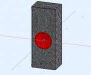
For now I don't intend to go down that route but at some point I might. I like the look of the waveguide I've shown and it seems promising enough for me to manufacture and test it.
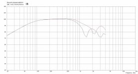
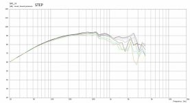
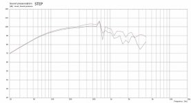
I think this graph (from the above linked thread) illustrates my contention that the output of these fairly simple simulations (in relative terms) is quite useful and pretty close to the mark already.
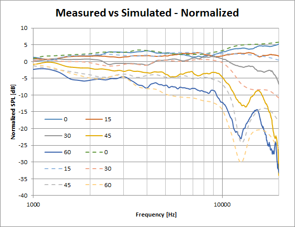
Below 10K the measured and predicted responses are quite similar and give a good idea of the directivity and potential issues allowing iterative improvements to the desired outcome. Above 10k and particularly with a dome tweeter all bets are off. But there are still off axis issues that are predicted at near the correct frequency if not quite the right magnitude.
With this speaker I am trying to build something that could be used successfully in various different rooms. Simulating a speaker in a specific situation and tailoring a solution to that specific case is a very valid route.
onni seemed to be quite happy to have your input and went quite a way towards the type of study you have suggested.
Using a small size axisymetric guide to allow circular symmetry would make the solve time quite reasonable.
For now I don't intend to go down that route but at some point I might. I like the look of the waveguide I've shown and it seems promising enough for me to manufacture and test it.
I think this graph (from the above linked thread) illustrates my contention that the output of these fairly simple simulations (in relative terms) is quite useful and pretty close to the mark already.
Below 10K the measured and predicted responses are quite similar and give a good idea of the directivity and potential issues allowing iterative improvements to the desired outcome. Above 10k and particularly with a dome tweeter all bets are off. But there are still off axis issues that are predicted at near the correct frequency if not quite the right magnitude.
With this speaker I am trying to build something that could be used successfully in various different rooms. Simulating a speaker in a specific situation and tailoring a solution to that specific case is a very valid route.
I have been working on woofer simulations with help from Don. It has taken a while to try and understand the results I was getting but I think I have something useful to work with now.
I have tried to represent the overall shape of the enclosure and have had to go to half symmetry. Fortunately simulating up to 4KHz, using a less detailed baffle and an Le Script meant the simulation times were very reasonable.

Two things affected the output from the simulator and to start with they made the results look pretty funky. The depth of the cone used for the woofer and the length of the rear chamber in the Le Script were the two factors. The length of the rear chamber created spikes in the response which can be removed by not specifying a length. Much like masking resonances in Hornresp.
The depth of the woofer cone was a guess based on the drawing in the datasheet and that also turned out to have done a good job of muddying the water. What this means is that the level of confidence in these simulations has to go down for now as I don't have the exact dimensions of the proposed woofer to make the simulations more accurate.
On the other hand what I was trying to look at was what effect did different woofer mounting methods have and I think the simulations answer that question reasonably well at least in a general way.
Any time the woofer is set back into the baffle it effectively looks like the woofer cone is deeper. A deeper woofer cone introduces a dip in the response so this needs to be considered carefully.
Don put me on to a paper by Joerg Panzer 'Radiation impedance of cones at high frequencies' which confirms that as the depth of the simulated woofer increases, the accuracy of the prediction goes down as frequency rises. The simulations of this sort of woofer depth are only reasonable up to 1.5K or so.

What I have simulated is the woofer in an Infinite Baffle. This gave the best response at the low end and the worst response at the upper end.
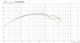
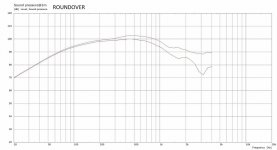
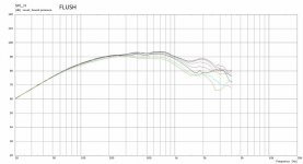
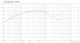
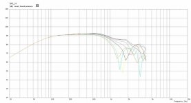
I have also simulated the driver mounted flush, set in 18mm with a 45 deg chamfer, an 18mm roundover and a 13mm vertical step. There is not a huge difference between the chamfer and roundover, most likely due to the limitations on the mesh making the two quite similar. Flush is impractical as the driver has a 13mm step up from the surround but it shows a worst case scenario for this situation. Diffraction off the edge of the basket.
I have attached some gif's to show the different simulations against each other.
1m On axis and 45 deg Horizontal
3m Horizontal 7.5 degree steps
I have tried to represent the overall shape of the enclosure and have had to go to half symmetry. Fortunately simulating up to 4KHz, using a less detailed baffle and an Le Script meant the simulation times were very reasonable.
Two things affected the output from the simulator and to start with they made the results look pretty funky. The depth of the cone used for the woofer and the length of the rear chamber in the Le Script were the two factors. The length of the rear chamber created spikes in the response which can be removed by not specifying a length. Much like masking resonances in Hornresp.
The depth of the woofer cone was a guess based on the drawing in the datasheet and that also turned out to have done a good job of muddying the water. What this means is that the level of confidence in these simulations has to go down for now as I don't have the exact dimensions of the proposed woofer to make the simulations more accurate.
On the other hand what I was trying to look at was what effect did different woofer mounting methods have and I think the simulations answer that question reasonably well at least in a general way.
Any time the woofer is set back into the baffle it effectively looks like the woofer cone is deeper. A deeper woofer cone introduces a dip in the response so this needs to be considered carefully.
Don put me on to a paper by Joerg Panzer 'Radiation impedance of cones at high frequencies' which confirms that as the depth of the simulated woofer increases, the accuracy of the prediction goes down as frequency rises. The simulations of this sort of woofer depth are only reasonable up to 1.5K or so.
What I have simulated is the woofer in an Infinite Baffle. This gave the best response at the low end and the worst response at the upper end.
I have also simulated the driver mounted flush, set in 18mm with a 45 deg chamfer, an 18mm roundover and a 13mm vertical step. There is not a huge difference between the chamfer and roundover, most likely due to the limitations on the mesh making the two quite similar. Flush is impractical as the driver has a 13mm step up from the surround but it shows a worst case scenario for this situation. Diffraction off the edge of the basket.
I have attached some gif's to show the different simulations against each other.
1m On axis and 45 deg Horizontal
3m Horizontal 7.5 degree steps
Attachments
Individual graphs of above plus IB curves
Attachments
-
 IB Woofer 1m.jpg72.1 KB · Views: 73
 -
 Driver Step 3m.jpg77.4 KB · Views: 75
 -
 Driver Step 1m.jpg73.9 KB · Views: 72
 -
 Driver Roundover 3m H.jpg76.8 KB · Views: 77
 -
 Driver Roundover 1m.jpg73.3 KB · Views: 78
 -
 Driver Flush 3m.jpg76 KB · Views: 79
 -
 Driver Flush 1m.jpg72.3 KB · Views: 77
 -
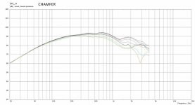 Driver Chamfer 3m.jpg76.6 KB · Views: 85
 -
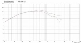 Driver Chamfer 1m.jpg73.2 KB · Views: 99
 -
 IB Woofer 3m.jpg76.9 KB · Views: 70
- Home
- Loudspeakers
- Multi-Way
- 2 way waveguide speaker build ABEC modelling