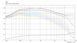
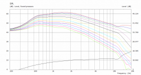
After some collaboration with another member offline I created a slightly different waveguide that I really like the look of so far. The Directivity is slightly rising but very even and with a very smooth response overall, virtually no axial ripple. The directivity looks like it will hand off nicely to the 15" woofer too.
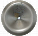
It looks like this, 470mm wide by 133mm deep
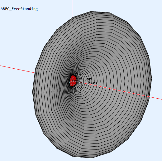


It looks like this, 470mm wide by 133mm deep
Attachments

Thanks ") At this point I don't want to post publicly the entire script as it would allow any unscrupulous person to undercut all of mabat's hard work and produce knock off "insert cheap overseas marketplace" with no effort required. For genuine DIY'ers I am less concerned and more willing to share.
At this point I don't want to post publicly the entire script as it would allow any unscrupulous person to undercut all of mabat's hard work and produce knock off "insert cheap overseas marketplace" with no effort required. For genuine DIY'ers I am less concerned and more willing to share.
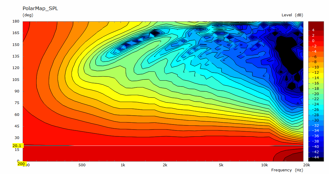
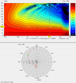
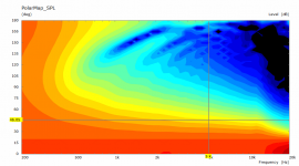
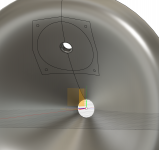
The beamwidth is easy to see at spot frequencies in the round polar chart attached below. I have marked in green the -6dB at 5K which is 50 deg. narrower from there and wider below but not by too much. The pattern is probably a little wider than needed and I might tweak it a little to be closer to 45 each way which is the coverage set in the config file. The parameters are quite interactive so it might not be quite that easy.
This is a 1.4" guide to match the Faital HF1440. The uptilt in the SPL or downtilt in the polar above 10K would be worse for a 2" guide as it is better for a 1" one.
At this point I don't want to post publicly the entire script as it would allow any unscrupulous person to undercut all of mabat's hard work and produce knock off "insert cheap overseas marketplace" with no effort required. For genuine DIY'ers I am less concerned and more willing to share.The beamwidth is easy to see at spot frequencies in the round polar chart attached below. I have marked in green the -6dB at 5K which is 50 deg. narrower from there and wider below but not by too much. The pattern is probably a little wider than needed and I might tweak it a little to be closer to 45 each way which is the coverage set in the config file. The parameters are quite interactive so it might not be quite that easy.
This is a 1.4" guide to match the Faital HF1440. The uptilt in the SPL or downtilt in the polar above 10K would be worse for a 2" guide as it is better for a 1" one.
Attachments
I ran a few alternatives and got the coverage to about 46 degrees each way by reducing the coverage angle to 38. This made the waveguide smaller which is good. I tried making it longer to load lower which worked but it made the pattern narrower in the 500 to 800Hz range where I think the woofer will cross and be 60 degrees or wider. So this seems to be a good compromise and might be just a little better than the previous one but with a slight kink at 10K that wasn't there before.
Attachments
are you going to model the taps in ABEC? I've tried a few different tap types in waveguides , but so far have been unable to come up with any design that didn't completely destroy the smooth pattern i've had with OS waveguides with massive amounts of diffraction.
tried lots of spread out small (0.8mm) holes as well as swept holes similar in design to EAW speaker (see anya or earlier stuff)
tried lots of spread out small (0.8mm) holes as well as swept holes similar in design to EAW speaker (see anya or earlier stuff)
I'm going to try, I don't know if I will succeed or what the result will be.are you going to model the taps in ABEC?
I'm going to try, I don't know if I will succeed or what the result will be.
Looking forward to this! At some point I want to design a Synergy-type speaker and was wondering if I could model it with ATH/ABEC. I think the sound source model is going to be more complicated which introduces the opportunity for reality to deviate from the sim. Maybe someone could take on the task of modeling a simple small woofer on an MEH and verify with measurements, until the reality matches the sim with some consistency.
Have you got any photos or measurements of what you tried?can't wait! I was too lazy to model them and make scripts for abec so I just printed them. really interested to see what abec shows.
The driver can be modelled with a Lumped element script which is pretty accurate for woofers, the cone on the ones I am using is quite shallow and I would likely use them only up to 800Hz or 1k which means the simulations should be quite realistic if I get the air volumes correct.Looking forward to this! At some point I want to design a Synergy-type speaker and was wondering if I could model it with ATH/ABEC. I think the sound source model is going to be more complicated which introduces the opportunity for reality to deviate from the sim. Maybe someone could take on the task of modeling a simple small woofer on an MEH and verify with measurements, until the reality matches the sim with some consistency.
The effect on the high frequencies will be seen without having to drive the woofer membrane as was done before with the woofer diffraction simulations.
The difficulty will be getting the mesh and interfaces right to avoid getting garbage results.
Yeah. I tried a few before this one. but I didn't have my process down, and i didn't keep measurements because I wasn't happy at all.
this one I printed 2 identical ones (one with holes, and one without) also threw out the measurements because they where meh.
the one without holes had a nice smooth CD fall in the response as I went off axis.
the ones with holes had pronounced widening between about 2.5k-8k. i've seen that same widening in some of batemans printed W.G.
have a few ideas that i still want to try, the classic 4 small holes. as well as covering the holes with a cover like I saw in another thread.
I'm kinda with Mabat, where I don't really want to do it unless its not gonna impact the base wave guide performance. seems even harder to do now that his waveguides are so freaking smooth!
Attachments
I don't think that will be possible if they are injected into the horn, I have been considering what other methods could be used, possibly something along the lines of Genelec's slot ported woofers but with a freestanding guide I'm not finding a way yet.I'm kinda with Mabat, where I don't really want to do it unless its not gonna impact the base wave guide performance. seems even harder to do now that his waveguides are so freaking smooth!
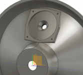
For my first try I'm just sticking with a 20mm port rounded on the front and chamfered on the back. If I can model this successfully in ABEC I'll have a better idea of whether this is worth taking further or not.
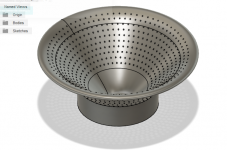
I'm not too surprised the cullender didn't work (but thanks for the image), I'm trying to follow mark100's direction where his ports further out had less impact.
Attachments
Intriguing ideas. Controlling diffraction at the mid port, as you are doing by using one small port, is probably a wise approach for home use. Though I'm not sure that anyone can tell you how much extra diffraction might be audible, when the WG starts off with the wonderfully low diffraction that it has.
*If* diffraction from a port like that is a significant concern (and measurement might beat simulation here, in time and effort), it should be possible to find good shapes for the port, perhaps inspired by MABATs work on the WG (within all the constraints of getting the other port properties right).
Recognizing that the amplitude of diffraction depends on the 2nd derivative of the profile, I would try shaping the WG-side of the port accordingly.
As an aside, if I could get a DEH (dual entry horn) to work like that, I'd use the mid to cover down an extra octave or so. That might free up a lot of design space to cross over to woofers that don't create huge problems at higher frequencies.
Ken
Hi Ken,
Good to have you here, you might also like some of the work being done by nc535 here Full range line array for wall or corner placement
Good to have you here, you might also like some of the work being done by nc535 here Full range line array for wall or corner placement
I have only modelled one port as I will be using symmetry in ABEC, the idea is that there will be 4 ports one for each midwoofer. In the first instance I am looking to see what the effect will be and decide from there if it is worth pursuing.Intriguing ideas. Controlling diffraction at the mid port, as you are doing by using one small port, is probably a wise approach for home use. Though I'm not sure that anyone can tell you how much extra diffraction might be audible, when the WG starts off with the wonderfully low diffraction that it has.
Part of my initial goal was to build a very low diffraction speaker so I am not keen to give that up unless the trade seems worthwhile. Building and measuring something like this will be quite a bit of effort that I am not ready for yet. I am nearly ready to run a simulation though*If* diffraction from a port like that is a significant concern (and measurement might beat simulation here, in time and effort), it should be possible to find good shapes for the port, perhaps inspired by MABATs work on the WG (within all the constraints of getting the other port properties right).
You will have to say this in English for me to have any hope of understanding, I do not speak Mathematics, but I would like to know what that means.Recognizing that the amplitude of diffraction depends on the 2nd derivative of the profile, I would try shaping the WG-side of the port accordingly.
The idea in this size horn is to cover from 100Hz up to 500 or 800Hz with the midwoofers and cross to the CD thereAs an aside, if I could get a DEH (dual entry horn) to work like that, I'd use the mid to cover down an extra octave or so. That might free up a lot of design space to cross over to woofers that don't create huge problems at higher frequencies.
I'm not too surprised the cullender didn't work (but thanks for the image), I'm trying to follow mark100's direction where his ports further out had less impact.
yeah the best result I had so far was actually from long thin slots that started about 50% of the way up the waveguide and went to the edge at an angle.
@kstrain. yes this is also what i'd like to do. just want to get the midrange down to 500-600hz then happy to have a woofer below. I can see that for pro sound its important to have a point source though the range. but i'm pretty sure geddes has said it doesn't matter much below a point for in room.
@fluid
I see you following best practices re' synergy mid ports but I caution you to simulate in HR first to get close before going on to ABEC. The length and diameter of the port do effect the response shape sometimes very strongly for mids and you want to check the particle velocity.
I see you following best practices re' synergy mid ports but I caution you to simulate in HR first to get close before going on to ABEC. The length and diameter of the port do effect the response shape sometimes very strongly for mids and you want to check the particle velocity.
Fluid,
apologies for the math-speak. I meant that as you trace along the curve, you want the slope to change as smoothly as possible.
For a sound wave of given wavelength, the slower the slope changes the less the diffraction. A sharp edge is worst, so the trick is figuring out which smooth curve is best, given that it has to bridge between two angles. That's essentially what MABAT is exploring when terminating the OS WG with smooth curves (and reducing response ripples that start from diffraction).
As the wavelength gets larger, diffraction from a fixed-size feature decreases, but the same smooth curve minimizes it for all wavelengths of interest.
I've no idea whether the amount of diffraction from the ports matters at all, but it struck me that they could be more rounded, as you have low diffraction as a goal.
I'd missed that you were planning four ports. It's not clear to me that makes sense for home use. If you introduce four sources of diffraction in an arrangement that's highly symmetrical about the center line of the WG, you risk boosting their effect by interference (leading to bigger ripples and stronger excitation of one or other of the higher order modes). For home use, I would tend to lose an octave of mid-range response at the low end, and settle for one port rather than four. I guess you could make a WG with four ports, and also make three plugs, and test both ways.
I'm keeping an eye on all the related threads, thanks. Good luck with your project!
Ken
As nc535 says, there are a bunch of factors that need to be taken into account to achieve the desired mid-range response - those take precedence over subtle changes in diffraction.
Last edited:
- Home
- Loudspeakers
- Multi-Way
- 2 way waveguide speaker build ABEC modelling