Glad to hear you are making progress, the LaScala has a tweeter
I have a mint pair of EV ST350Bs that could be set on top of your 511Bs.
I will keep that in mind. I do have a few tweeters to play with at hand, so I may play around a bit first. It actually sounds great as is though. Mind you, I can only good hear to about 14K on a good day.
One thing I notice is the reversed polarity of your mid driver in post #50. For a horn bass + horn mid the A7-500 and LaScala crossovers do not reverse the polarity.
The Hiraga A7 version and the one Pano posted in post #57 do reverse polarity.
Have you tried both connections to have a preference?
The Hiraga A7 version and the one Pano posted in post #57 do reverse polarity.
Have you tried both connections to have a preference?
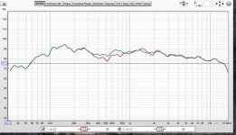
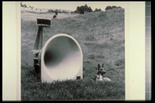
I did a bit of searching a while back, and confirmed yesterday that the minimum set back for La Scala is around 24 inches. the FH-1 a bit bigger, so I set it at 27 inches back. I attached a REW screenshot of the two traces together. Green is reversed, and red is normal. This is in reference to the Riggle and Hiraga schematics, which reverse the connection, so that means that the connection is actually not reversed electrically. I think. I have to look at it again. The green trace looks better, but I haven't listened to them both yet.
Attachments
![IMG_1452[3885].jpg](/community/data/attachments/787/787880-f61cd896468b9db097c0be5a25742093.jpg)
For a LaScala the bass bin inside is approximately 24 in deep, 22 in wide and then about 4 inches from the woofer flange to dust cap. so 24+11+4= 39 inch path.
The FH1 is about the same depth but about 30 in wide, so 24+15+4=43 inch path.
Also if you put the horn way back on the top you will get strange early reflections.
The FH1 is about the same depth but about 30 in wide, so 24+15+4=43 inch path.
Also if you put the horn way back on the top you will get strange early reflections.
One thing I notice is the reversed polarity of your mid driver in post #50. For a horn bass + horn mid the A7-500 and LaScala crossovers do not reverse the polarity.
The Hiraga A7 version and the one Pano posted in post #57 do reverse polarity.
This is a source of ongoing confusion, so a picture always helps some folks.
")
A composite for the N500-8, N800-8. Notice that the drivers are acoustically in phase when the +power connects to the - [2] HF terminal when the motors are in line [A7-500, etc.]: https://lh3.googleusercontent.com/p...xidZc2936MXweizmeOAzplxIFskkAr_3I6sRsVUmGr7vQ
GM
Last edited:
An externally hosted image should be here but it was not working when we last tested it.
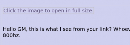
Hello GM, this is what I see from your link? Whoever did create that link forgot to say the "for the 811 horn the crossover point is 800hz.
That assumes 8 ohm woofer and tweeter. tizman has a 4 ohm woofer in a folded horn.
Last edited:
Greets!
Interesting, it's been around for a long time and never noticed it, but then it was for Altec folks who would assume it.
Regardless, you referenced the A7-500, so posted its XO for the acoustic phasing Vs wiring polarity with nothing else WRT to components either stated or implied.
GM
Interesting, it's been around for a long time and never noticed it, but then it was for Altec folks who would assume it.
Regardless, you referenced the A7-500, so posted its XO for the acoustic phasing Vs wiring polarity with nothing else WRT to components either stated or implied.
GM
For a LaScala the bass bin inside is approximately 24 in deep, 22 in wide and then about 4 inches from the woofer flange to dust cap. so 24+11+4= 39 inch path.
The FH1 is about the same depth but about 30 in wide, so 24+15+4=43 inch path.
Also if you put the horn way back on the top you will get strange early reflections.
This is the quote by ChrisA on the Klipsch forums that I used to set the offset of the 511B from the front of the bass bin...
“For your La Scala bass bin, the path length looks to be close to 33-34 inches, looking at a drawing that someone did for a 1977 model. You would need to move the midrange driver/horn throat back by at least that amount from the front face of the bass bin to be on top of the bass bin delay. As I mentioned above, you need to be within a 1/4 wavelength of that distance at the crossover point, so if you're crossing with a center frequency of 400 Hz, that's about 8 1/2 inches less than that total path length distance. So the minimum offset of the midrange driver exit to the bass bin front face is 24.5 inches. I measured my K-400 midrange horn at ~21.5 inches.”
My speaker is crossed over at 620 HZ, so the 1/4 wavelength that I need to stay within is more precise than if it were crossed over at 400 HZ. I just plunked it down at 28 inches as a ballpark. I know that it will require fine tuning.
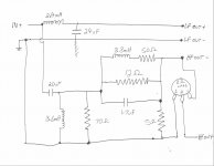
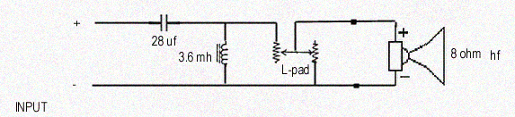
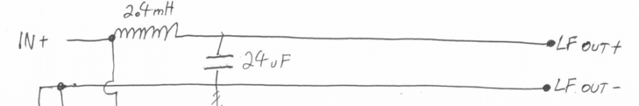
For quick reference here is the modified Hiraga crossover I built and the A7-500 crossover. I took out the 5 and 70 Ohm resistors, the entire LCR in the HF section, and the L-Pad is still there but not required or used, leaving the two inductors and the two capacitors.
Attachments
"the path length looks to be close to 33-34 inches" that would be the length of the wood horn. I also added 4 inches for the woofer mounting flange to dust cap.
So the FH1 is 39 in path length + 4.
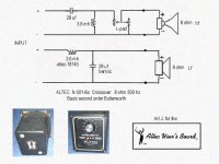
I attached the A7-500 diagram for use of the HF section. As you use a 4 ohm woofer the A7 LF does not apply.
Perhaps a combination of the LF in your pix and A7 HF.
So the FH1 is 39 in path length + 4.
I attached the A7-500 diagram for use of the HF section. As you use a 4 ohm woofer the A7 LF does not apply.
Perhaps a combination of the LF in your pix and A7 HF.
Attachments
Mr Glyph, is this what you see? GMs image is Error 403 for me.
Yes, today the link is 403 for me also. Last night it opened to my attachment below. This is why I added the 811 for 800cps comment.
Attachments
Last edited:
Interesting! Still works for me, but maybe this link will be better long term: http://www.audioheritage.org/vbulletin/attachment.php?attachmentid=14547&stc=1&d=1144022528
.......and for completeness, when the A7 uses the 811/800 Hz XO it's an A7-8.
GM
.......and for completeness
, when the A7 uses the 811/800 Hz XO it's an A7-8.GM
I am also in the same boat like you... Hope next week i will be able to sort it out with the suggestions received.
Hello All.
I realized almost immediately that there was an issue, as there was obviously too much bass in the output.
I need to attenuate the bass by around 6-7 DB. I added an L-Pad on the output of the Hiraga, as per Pete Riggle's modification of the Hiraga crossover, in order to control the treble, but there is not enough treble even with the L-Pad set to let all the power through to the HF section.
This is the link for the Hiraga crossover as modified by Pete Riggle....
Altec A7 Voice Of Theatre Speakers - Vertical Tracking Angle on the Fly (VTAF)
Well I did not have good luck with the published Hiraga crossover and my A5. That has always puzzled me, as I heard and loved the original that Jean Hiraga and I built. Different drivers, I guess.
The published crossover is a staring place, but I ended up a goodly distance away from it.
Really the best way is to measure, measure, measure then build your own. Then tweak it more.
The published crossover is a staring place, but I ended up a goodly distance away from it.
Really the best way is to measure, measure, measure then build your own. Then tweak it more.
- Status
- This old topic is closed. If you want to reopen this topic, contact a moderator using the "Report Post" button.
- Home
- Loudspeakers
- Multi-Way
- Jean Hiraga Altec A5 Crossover modification