Hi All,
With a previous speaker project finished and out of the way now, it's time to start on the next project - a large floor standing three way system which has been on the boil conceptually for many years which I now have all the drivers for.
While I wait for a chance to start on building cabinet etc and get more detailed (in box) measurements, I've been spending a bit of time doing some preliminary crossover design experimentation and have run into a bit of a hurdle with the woofer crossover suffering from excessive peaking.
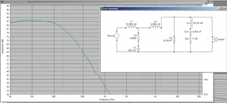
The Woofer is a Visaton W300S 8 ohm, (12") and the intention is to put it into a large bass reflex box of approx 110-120 litres tuned to 25Hz. The woofer will be close to the floor for optimal mid/upper bass performance. Here's a basic box sim in Vituixcad:

I'd describe this as an early gradual roll off response, which is 3dB down at about 35Hz and 6dB down at about 29Hz.
The original intention was to passively cross it over at 250Hz with a L/R 4th order accoustic roll off, but this is proving a real challenge due to the interaction of the woofer impedance.
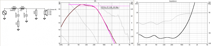
Here is the current circuit:
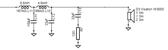
The issue I'm seeing is a huge 4dB peak in the filter response centered around 80Hz, along with a minimum input impedance of about 4 ohms centered slightly above this:

This is presumably a combination of the capacitive reactance of the woofer between 50-150Hz, and the low pass filter acting as a resonant impedance transformer - by causing the input impedance to go well below the woofers actual impedance (6.8 ohms DCR, about 8 ohms above resonance) it is effectively "boosting" the filters output 4dB above the input, and obviously this is undesirable.
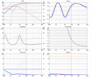
I was still able to manually tune the response of the filter to get a spot on 4th order L/R accoustic low pass filter response (theoretical target is the purple curve) including predicted baffle step loss, and also a flat summed resonse from about 80Hz up with good phase tracking to the midrange driver, however I'm still not happy about this situation for a number of reasons:
1) I don't like the impedance dipping down to 4 ohms in the bass. Yes a lot of speakers do this (although usually by being a 2 1/2 way or similar) but it's an unnecessary strain on the amplifier and also makes the impedance variation across the spectrum greater thus making the tonal balance of the speaker more sensitive to speaker cable resistance / amplifier output impedance variations, something I'd like to minimise.
2) While my midrange and tweeters are quite sensitive (95 / 96dB respectively) this artificial and unwanted voltage sensitivity boost in the upper bass region of the woofer doesn't leave me with much attenuator wiggle room for the mid/treble networks to get the tonal balance correct, especially when the near floor mounting of the woofer will give it about another 2dB of gain vs the high mounted midrange.
3) The artificial peak near 80Hz completely changes the low frequency roll off shape of the bass, changing it from an early gradual rolloff with a smooth gradual curve to a sharper more abrupt rolloff which is now 3dB down at 56Hz and 6dB down at 44Hz - a far cry from the un-modified driver response of 35Hz and 29Hz respectively.
So what can be done about it ? In a passive network, not a lot it seems, although I'm hoping someone has an idea I haven't thought of...
A few thoughts:
1) I could in theory add a series tuned trap to notch out the 42Hz impedance peak, however that is totally infeasible as the capacitor and coil values would be humoungous and expensive, with the resistor dissipating a huge amount of power.
2) I could shunt the woofer with say 33 ohms to flatten the impedance curve out a bit near resonance. Despite adding a shunt the minimum input impedance actually increases to about 4.6 ohms due to the impedance transformation effect. This also avoids a capacitor and coil and does give some improvement, however the resistor still disspiates a lot of power at the frequencies where the woofer impedance is high, for relatively minimal gain in the response. (The peak is reduced by about 1dB)
3) I could increase the crossover frequency a bit to get further away from the impedance peak - if I increase it from 250Hz to 300Hz the peak drops by 1dB or so but I'd hardly call that fixed, and I don't want to go any higher than 300Hz.
Other than that I'm out of ideas..... anyone else have any ? And no, "use an active crossover" isn't an option.
It seems that this must be a fairly common problem with passive woofer crossovers ? On my last 2 way design the baffle step correction did interact a little bit with the woofer's impedance resulting in a broad 1.5dB peak around 100Hz, however this wasn't harmful in that design as the woofer was high mounted (being a 2 way) so would usually have a suppressed output in the upper bass due to room interactions anyway.
But in this design I deliberately want the woofer close to the floor for increased mid/upper bass response, so I don't want to add an additional big peak in the midbass due to the crossover itself, and I can't seem to tune out this 4dB peak without destroying the accoustic low pass function.
With a previous speaker project finished and out of the way now, it's time to start on the next project - a large floor standing three way system which has been on the boil conceptually for many years which I now have all the drivers for.
While I wait for a chance to start on building cabinet etc and get more detailed (in box) measurements, I've been spending a bit of time doing some preliminary crossover design experimentation and have run into a bit of a hurdle with the woofer crossover suffering from excessive peaking.
The Woofer is a Visaton W300S 8 ohm, (12") and the intention is to put it into a large bass reflex box of approx 110-120 litres tuned to 25Hz. The woofer will be close to the floor for optimal mid/upper bass performance. Here's a basic box sim in Vituixcad:
I'd describe this as an early gradual roll off response, which is 3dB down at about 35Hz and 6dB down at about 29Hz.
The original intention was to passively cross it over at 250Hz with a L/R 4th order accoustic roll off, but this is proving a real challenge due to the interaction of the woofer impedance.
Here is the current circuit:
The issue I'm seeing is a huge 4dB peak in the filter response centered around 80Hz, along with a minimum input impedance of about 4 ohms centered slightly above this:
This is presumably a combination of the capacitive reactance of the woofer between 50-150Hz, and the low pass filter acting as a resonant impedance transformer - by causing the input impedance to go well below the woofers actual impedance (6.8 ohms DCR, about 8 ohms above resonance) it is effectively "boosting" the filters output 4dB above the input, and obviously this is undesirable.
I was still able to manually tune the response of the filter to get a spot on 4th order L/R accoustic low pass filter response (theoretical target is the purple curve) including predicted baffle step loss, and also a flat summed resonse from about 80Hz up with good phase tracking to the midrange driver, however I'm still not happy about this situation for a number of reasons:
1) I don't like the impedance dipping down to 4 ohms in the bass. Yes a lot of speakers do this (although usually by being a 2 1/2 way or similar) but it's an unnecessary strain on the amplifier and also makes the impedance variation across the spectrum greater thus making the tonal balance of the speaker more sensitive to speaker cable resistance / amplifier output impedance variations, something I'd like to minimise.
2) While my midrange and tweeters are quite sensitive (95 / 96dB respectively) this artificial and unwanted voltage sensitivity boost in the upper bass region of the woofer doesn't leave me with much attenuator wiggle room for the mid/treble networks to get the tonal balance correct, especially when the near floor mounting of the woofer will give it about another 2dB of gain vs the high mounted midrange.
3) The artificial peak near 80Hz completely changes the low frequency roll off shape of the bass, changing it from an early gradual rolloff with a smooth gradual curve to a sharper more abrupt rolloff which is now 3dB down at 56Hz and 6dB down at 44Hz - a far cry from the un-modified driver response of 35Hz and 29Hz respectively.
So what can be done about it ? In a passive network, not a lot it seems, although I'm hoping someone has an idea I haven't thought of...
A few thoughts:
1) I could in theory add a series tuned trap to notch out the 42Hz impedance peak, however that is totally infeasible as the capacitor and coil values would be humoungous and expensive, with the resistor dissipating a huge amount of power.
2) I could shunt the woofer with say 33 ohms to flatten the impedance curve out a bit near resonance. Despite adding a shunt the minimum input impedance actually increases to about 4.6 ohms due to the impedance transformation effect. This also avoids a capacitor and coil and does give some improvement, however the resistor still disspiates a lot of power at the frequencies where the woofer impedance is high, for relatively minimal gain in the response. (The peak is reduced by about 1dB)
3) I could increase the crossover frequency a bit to get further away from the impedance peak - if I increase it from 250Hz to 300Hz the peak drops by 1dB or so but I'd hardly call that fixed, and I don't want to go any higher than 300Hz.
Other than that I'm out of ideas..... anyone else have any ? And no, "use an active crossover" isn't an option.
It seems that this must be a fairly common problem with passive woofer crossovers ? On my last 2 way design the baffle step correction did interact a little bit with the woofer's impedance resulting in a broad 1.5dB peak around 100Hz, however this wasn't harmful in that design as the woofer was high mounted (being a 2 way) so would usually have a suppressed output in the upper bass due to room interactions anyway.
But in this design I deliberately want the woofer close to the floor for increased mid/upper bass response, so I don't want to add an additional big peak in the midbass due to the crossover itself, and I can't seem to tune out this 4dB peak without destroying the accoustic low pass function.
Attachments
Last edited:
"4th order why" - because that's the design path I want to follow."L/R 4th order" - why?, the WS300 should be OK with 1st or 2nd order, & the Zobel is pointless with caps that big in the preceding filter
L/R 4th order is the target design for both crossover points for quite a number of reasons.Yes, the W300S can work OK with 2nd order at 300Hz as well - I used them like that for a number of years. They are pretty much flat up until 1Khz, but do have quite a big resonance at 2Khz. However I think imaging could be improved with a tighter filter, especially when the drivers will be spaced some distance apart. (Nearly half a wavelength at 250Hz)
An issue with going down to 2nd order is that the midrange driver will be in a small sized enclosure which gives a 2nd order mechanical high pass response at about 250Hz, supplimented by a 2nd order electrical high pass filter, the sum of the mechanical and electrical roll offs should be pretty close to a 4th order L/R accoustic response. (I can get very close in the simulation just with the right L/C and midrange box volume)
I can't switch that to a 2nd order accoustic response because that would mean no high pass filter at all for the midrange driver...
Another thing I'd note is that changing the filter to 2nd order doesn't improve the situation with the unwanted peak at 80Hz.
Last edited:
You didn't state what your mid is, so I can't fully comment. But you have only two options: choose an higher crossover point to the mid (this will also have the additional advantage on using an LR2 target, see below), or opt to using an active crossover between bass and mid. Find a plate amp with customizable crossover type and point, and phase and you're done.
Ralf
I don't think so, imaging should be more related to baffle size, highs and diffraction.However I think imaging could be improved with a tighter filter, especially when the drivers will be spaced some distance apart. (Nearly half a wavelength at 250Hz)
I understand your situation, but did you simulate the cone excursion of the mid without crossover? How about to adapt the mid box volume in order to achieve the LR2 target with only a cap?.An issue with going down to 2nd order is that the midrange driver will be in a small sized enclosure which gives a 2nd order mechanical high pass response at about 250Hz, supplimented by a 2nd order electrical high pass filter, the sum of the mechanical and electrical roll offs should be pretty close to a 4th order L/R accoustic response. (I can get very close in the simulation just with the right L/C and midrange box volume)
Ralf
The "Midrange" is a Tangband W8-1772 in an approx 10 litre enclosure.You didn't state what your mid is, so I can't fully comment.
As I mentioned earlier, I'm building a passive design, so an active crossover is off the table.But you have only two options: choose an higher crossover point to the mid (this will also have the additional advantage on using an LR2 target, see below), or opt to using an active crossover between bass and mid. Find a plate amp with customizable crossover type and point, and phase and you're done.
I'm willing to go up to 300Hz crossover but no higher, and for various reasons I'd prefer to stick to 250Hz if possible.
There are many factors that affect imaging. Excessive "spillover" from the woofer at higher frequencies due to shallow rolloff is also detrimental to imaging especially when the drivers will be 1/2 wavelength apart at 250Hz.I don't think so, imaging should be more related to baffle size, highs and diffraction.
I agree baffle size and diffraction effects are major factors as well. The baffle will be wide - approx 45 to 50cm. (Not quite decided yet, depends on required internal volume, and final box height and depth)
Cone excursion without a crossover would be tolerable due to the small closed box (the 1772 has an Xmax of about 3mm) however it's very unsatisfactory in other ways.I understand your situation, but did you simulate the cone excursion of the mid without crossover?
A major reason to build a 3 way system is to relieve the midrange driver of bass duties. Even if the excursion is limited by the closed box the motor system would still be subjected to the full bass signal which is not ideal from the point of view of midrange fidelity. Driving a thin paper cone hard with bass in a small closed box is not a good idea.
Also the input impedance of the full system would be very low in the bass for no good reason. I'm already struggling with the input impedance being too low due to the peaking affect this thread is about.
I had considered that, but it would require a much larger midrange volume (>20 litres) to bring the resonance of the driver an octave below the electrical crossover point, which would subtract significant bass enclosure volume. Even then, the response would not follow a LR2 curve sufficiently low enough in frequency to give good phase tracking and summing. I'm trying to ensure the best possible phase tracking between woofer and mid in the crossover region.How about to adapt the mid box volume in order to achieve the LR2 target with only a cap?.
From the point of view of the midrange driver (and box volume efficiencies) exploting the mechanical roll off of the driver in a small box as half of the L/R transfer function is a useful optimisation - it minimises the box volume consumed, and it lets you get a 4th order accoustic roll off with a simple 2nd order electrical filter.
This approach was in mind from the beginning and is one reason why I chose the 1772 with its very low Qts of 0.27. (It can be used in a very small closed box giving a high resonance frequency while still keeping a relatively low Qtc that will give close to what is needed for half of a L/R 4th order response)
With a 250Hz crossover point I can get very close to a 4th order L/R total response, if I move the crossover up to 300Hz then the response deviates a lot more from the desired target as I can't shift the resonance frequency of the driver too much higher (even smaller box) without the Qtc going too high. (Also if the box gets too small it leaves not enough room for padding/damping material) From the point of view of the midrange driver/crossover, 200-250Hz is about optimal for the crossover frequency.
BTW I'm trying not to decend into a full blown design thesis of the whole speaker in this thread, I'm mainly interested in trying to solve the peaking issues in the woofer crossover. While I've had a little bit of woofer crossover peaking like this in previous designs it seems a bit extreme in this case, and I'm not sure why. I can't be the only person to ever use a passive 4th order L/R crossover on a woofer, so there must be something that can be done to improve the situation.
Last edited:
Hello Simon.
At the risk of asking something rather stupid, but: have you used the Optimizer in VCad, or is this an "educated guess/manual optimization" lowpass so far? Silly as it may sound as approach, but in LspCad 5.2 I have good experiences with throwing in an extra half hand of components and then let the Optimizer handle the x/o optimization with brute force.
At the risk of asking something rather stupid, but: have you used the Optimizer in VCad, or is this an "educated guess/manual optimization" lowpass so far? Silly as it may sound as approach, but in LspCad 5.2 I have good experiences with throwing in an extra half hand of components and then let the Optimizer handle the x/o optimization with brute force.
OK, so you considered all the options, but are unwilling to loose some constraints. Unfortunately, speaker design is an exercise of compromises, so IMHO you are on a dead end unless you change drivers and/or constraints. Your only other way could be an impedance flattening circuit, I've never used one so I never studied pros and cons. I had a quick search have a look here: Impedance Equalization - DIY-loudspeakers.com
I still think that an LR4 slope is overkill, and you can easily achieve an LR2 slope good enough for the mid maybe with a combination of many things: a slightly higher crossover point, a slightly larger box and a larger enough cap that acts more as a bass suppression than an additional one-order HP filter.
Ralf
I still think that an LR4 slope is overkill, and you can easily achieve an LR2 slope good enough for the mid maybe with a combination of many things: a slightly higher crossover point, a slightly larger box and a larger enough cap that acts more as a bass suppression than an additional one-order HP filter.
I'm not sure that is not entirely true. The midrange fidelity can be ruined if the driver effectively plays the bass, but if the bass is suppressed by the acoustical filter (the HP filter provided by the box), the driver plays only the midrange, so you won't have doppler effect and IM distortion.A major reason to build a 3 way system is to relieve the midrange driver of bass duties. Even if the excursion is limited by the closed box the motor system would still be subjected to the full bass signal which is not ideal from the point of view of midrange fidelity. Driving a thin paper cone hard with bass in a small closed box is not a good idea.
Ralf
I haven't had much luck with the automatic optimizer in VCad to be honest, so I usually hand optimise the values against the target curves, which really doesn't take that long when you have a good feel for a network and can see feedback in realtime.Hello Simon.
At the risk of asking something rather stupid, but: have you used the Optimizer in VCad, or is this an "educated guess/manual optimization" lowpass so far? Silly as it may sound as approach, but in LspCad 5.2 I have good experiences with throwing in an extra half hand of components and then let the Optimizer handle the x/o optimization with brute force.
In many situations, including this one, the optimiser seems to completely loose the plot and end up with a far worse result than what I can hand optimise in just a couple of minutes. I think the author himself has said that the current optimiser algorithm is fairly simple and somewhat limited in scope.
It's not clear what constraints you think removing will help ? You seem keen on a 2nd order filter but changing the woofer to a 2nd order slope doesn't help the issue - I've already tried it. The impedance peak is still too close to the crossover frequency and still results in a peak.OK, so you considered all the options, but are unwilling to loose some constraints. Unfortunately, speaker design is an exercise of compromises, so IMHO you are on a dead end unless you change drivers and/or constraints.
An impedance flattening circuit would work but the component values are just too large to be feasible and the power dissipation would be very high since the resistor has to dissipate nearly all the power at the impedance peak. It could be done actively of course but then why not just do the whole thing active.Your only other way could be an impedance flattening circuit, I've never used one so I never studied pros and cons. I had a quick search have a look here: Impedance Equalization - DIY-loudspeakers.com
I'm not against 2nd order L/R for the woofer to midrange crossover, it's my "plan B" (midrange to tweeter will remain 4th order) however if it doesn't help with the midbass peak issue and actually makes the midrange crossover more difficult (larger midrange enclosure and a compromise roll off slope that isn't a proper 2nd order L/R) then I don't see the point to be honest.I still think that an LR4 slope is overkill, and you can easily achieve an LR2 slope good enough for the mid maybe with a combination of many things: a slightly higher crossover point, a slightly larger box and a larger enough cap that acts more as a bass suppression than an additional one-order HP filter.
Whether the cone moves much or not due to being physically restrained by the small box, the motor system is still subject to the high current flow of the bass frequencies, this can introduce distortion and a lot of unnecessary voice coil heating which would cause Re to change with temperature affecting things like the impedance of the driver at crossover frequencies - an effect to be avoided.I'm not sure that is not entirely true. The midrange fidelity can be ruined if the driver effectively plays the bass, but if the bass is suppressed by the acoustical filter (the HP filter provided by the box), the driver plays only the midrange, so you won't have doppler effect and IM distortion.
As I mentioned earlier it's also not a good idea to drive the driver hard with bass while restrained by a small closed box when it has a very thin paper cone. (Mms is only 9 grams...) The cone is not built for that kind of mechanical stress. If it's going to be used in such a small box it needs an electrical high pass filter. Whether single order is enough I'm not sure.
The crossover point. You don't want to change it, don't want to go active and don't want to use an impedance flattening circuit, so... You are stuck with the bass peak and need to accept it.It's not clear what constraints you think removing will help ?
Maybe I wasn't clear enough. Changing slope won't help you with the bass peaking issue, but all else being equal, I think that an LR4 slope is overkill, not even considering the Zobel that IMHO is probably useless. But if an LR4 filter works for you, even considering the added parts to the LR2 filter, then it is OK.You seem keen on a 2nd order filter but changing the woofer to a 2nd order slope doesn't help the issue
For the mid-tweeter crossover an LR4 filter will be in many circumstances the ideal one.
Have you tried to just add a single cap to the mid just to block the bass but not changing (too much) the acoustical slope defined by the box?
Ralf
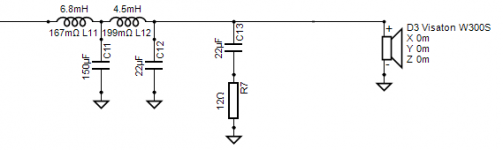
Hi Simon, I did a little modeling with a completely different driver, but got similar results to what you are showing. It looks like to tame it you need a resonant peak filter at least on the upper impedance peak.
For the test files I had it needed a substantial filter to tame it (resonant peak at 57Hz). approx 17mH - 450uF - 8 ohms .
I suspect if you want to get this to work you are going to need to so something similar. The above was calculated by speaker workshop for the zma and frd I had and it was spot on, and completely got rid of the peaking.
Tony.
Sure, no problem.Simon, would you post your data files, maybe others could take a shot at it. I know I've done this before but I don't want to guess whether it fits into the constraints in this case.
I've attached a zip of the frequency response (VCad .txt format) and impedance (zma format) in a zip file.
A couple of notes about these files - the impedance curve is a simulation from VCad's enclosure simulator for the proposed box tuning since I don't have a box yet to measure an impedance curve from...
Likewise the frequency response is a splice between manufacturers published response (>500Hz) and the simulated low frequency response in VCad's enclosure simulator, including baffle diffraction for the proposed baffle and driver location, also calculated in VCad. Hence it's a simulated farfield response rising 6dB from bass to midrange.
Of course when I get an actual prototype cabinet built I will be switching over to working from real measurements, but this gives me a rough approximation to work with in the meantime to help me see whether I'm going in the right direction or not and what challenges I might face - with the impedance peak issue being something it has helped me discover already.
Attachments
See the frequency response and impedance curves attached in my previous post if you want to try modelling with the same data I'm using.Hi Simon, I did a little modeling with a completely different driver, but got similar results to what you are showing. It looks like to tame it you need a resonant peak filter at least on the upper impedance peak.
Ouch. That's pretty much what I expected - infeasibly high values. Not only is that capacitor value huge (I'm already sweating about the size of the ~150uF cap I might need for the low pass filter if I go 4th order) that 17mH inductor would have to carry a lot of current at bass frequencies where the notch is most active, so could be prone to saturation if it was cored, and if it wasn't it too would be huge.For the test files I had it needed a substantial filter to tame it (resonant peak at 57Hz). approx 17mH - 450uF - 8 ohms .
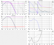
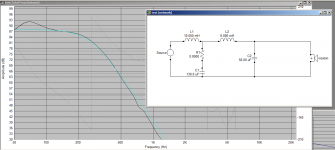
It's even worse with your zma.. attached as proof it can work but 46mH is not a practical size... There may be another way to deal with it though...
edit: added second pic without the resonant peak filter for comparison.
Tony.
edit: added second pic without the resonant peak filter for comparison.
Tony.
Attachments
Last edited:
I'm notching the hell out of those bumps in the bass region. I'm buying wire and wind my own coils. Copper wire costs 10euros/kg so that's cheap. For testing i've reused burned (that's why the plastic former is a bit deformed) regular EI transformer core. I wound 54mH with 0.6mm wire by hand on transformer core by mistake. I had to unwind three layers to get to 16mH that i needed. Dip the plastic former in laquer and voila. PS i don't have large hands.


For caps use two 100V polarized elcos connected back to back like this --|(--)|-- it's a notch filter at 80Hz anyways. Notch such as this is working for few years now in Kef R300's i reworked and with a guy who is not being gentle to them (he listens his music with lots of bass very loud). Works like a charm.
For caps use two 100V polarized elcos connected back to back like this --|(--)|-- it's a notch filter at 80Hz anyways. Notch such as this is working for few years now in Kef R300's i reworked and with a guy who is not being gentle to them (he listens his music with lots of bass very loud). Works like a charm.
Last edited:
I'm not sure that is not entirely true. The midrange fidelity can be ruined if the driver effectively plays the bass, but if the bass is suppressed by the acoustical filter (the HP filter provided by the box), the driver plays only the midrange, so you won't have doppler effect and IM distortion.
Ralf
I agree with Ralf here... Yes it is true that in the ideal world you would want to remove the bass frequency voltage and current from the midrange voice coil, it is far more important to remove the bass frequency cone displacement. And your small sealed box is providing a 12 dB/octave filter all by itself.
Another thing to consider: a + 4dB peak at 80 Hz is actually pretty mild. In a real room with real modes, you will have larger peaks and valleys just due to normal room response modes. In the USA, most homes are built with 8 ft ceilings, and this translates into a 1/2 wavelength frequency of 70 - 72 Hz. We typically have 10 dB "problems" at this frequency, which is usually a cancellation but can sometimes be a peak. I am guessing you are in the UK, and I don't know what kind of room you are in, but I am sure it will have various peaks and dips between 20 Hz and 200 Hz.
The best way to handle bass frequency room response problems is with an electrical solution, such as DSP... and if you are using DSP anyway, your small 4 dB peak at 80 Hz can easily be handled.
Without room-response DSP, I doubt you will even be aware of a 4 dB peak at 80 Hz. I bet it will sound quite marvelous as is...
Are you refering to just a straight box sim (driver driven directly, no crossover) or box sim + 4th order L/R low pass at 250Hz ?Simmed the WS300 in Unibox (120L, 25Hz), it shows a peak at 82 Hz, but only 0.6dB. It disappears with increased damping / box size.
If it's just a straight driver/box sim then yes, there is almost no peaking with a smooth gradual low frequency roll off. The peaking I'm having trouble with discussed in this thread is introduced by the low pass filter and isn't present with the driver by itself.
Or if your sim did in fact include a passive low pass filter as well can you share the circuit and values you used ?
Last edited:
I seem to have come up with three observations. Firstly, the inductor resistance seems to be a useful tool both in terms of the resonance and the sensitivity.
Secondly, in this example I'm using a 10 ohm parallel resistor and the impedance still shows as being above 5 ohms. In fact reducing this resistance will in some circumstances at some frequencies actually increase the impedance as a result of reducing the phase angle of the filter load, if you look close enough.
The other thing, if I were to do this again is to reduce the target sensitivity to the level at 110Hz, and let the 70Hz peak ride because not only is it a place where such a peak can be tolerated, it is also workable with the room.
Attachments
- Status
- This old topic is closed. If you want to reopen this topic, contact a moderator using the "Report Post" button.
- Home
- Loudspeakers
- Multi-Way
- Passive woofer crossover peaking issues