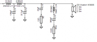
Doing a little more experimenting I came up with a slightly more practical resonant peak filter. This is probably doable. (all inductors are erse laminated core 16awg available at PE) The tradeoff for smaller inductor is bigger cap. Won't be cheap though.
I'm curious about why no active, is it philosophical, or maybe a design challenge?
Tony.
I'm curious about why no active, is it philosophical, or maybe a design challenge?
Tony.
Attachments
I have been working on a similar problem with a ongoing project (second order filter though), and went with impedance flattening LCR of the woofer resonance, and series resistance on the cap to gnd just like in the previous example, that made it a lot better, but it's still peaking a little bit compared to the raw driver response, because I had to 'twist' the phase a little to match with the mid.
For the impedance correction air wound coils with thin wire are not that expensive, in my case the resistance of the coils (needed two) matched the needed resistance. I got Jantzen coils from here: Kamm Lautsprecher Internet-Shop
For the impedance correction air wound coils with thin wire are not that expensive, in my case the resistance of the coils (needed two) matched the needed resistance. I got Jantzen coils from here: Kamm Lautsprecher Internet-Shop
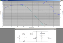
After playing around in Vituixcad with a notch here's what I came up with - similar to yours, which I hadn't seen until later - although mine has a zobel which changes the stop band response significantly and therefore all the other values as well:Doing a little more experimenting I came up with a slightly more practical resonant peak filter. This is probably doable. (all inductors are erse laminated core 16awg available at PE) The tradeoff for smaller inductor is bigger cap. Won't be cheap though.
The notch has a Q of exactly 1.0, centre frequency of 49Hz, and flattens the impedance curve perfectly. The blue line is the filter response, the red line is the response with the peak with the notch disconnected, and the purple line is the target response which you almost can't see because it overlays so closely even below -50dB.
Minimum impedance is still 5.4 ohms at 22Hz, but rises significantly above that and is above 6.8 ohms above 37Hz)
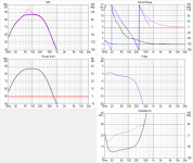
It's interesting to consider that not only is the filter applying a 4th order low pass response, baffle step correction (rollover point 230Hz) is also built in with no additional components just by retuning the low pass filter from the theoretical.
When I tried to do the same thing with a 2nd order filter I was only able to get a rough approximation not the very close match I get with 4th order. It just goes to show that the more degrees of freedom you get with a higher order filter can be put to good advantage in shaping the response.
") (I made use of that shaping ability extensively in my last design)
(I made use of that shaping ability extensively in my last design)So it's certainly possible to achieve the target response passively but 363uF and 28.9mH are quite daunting and would require a (by-passed) bipolar electrolytic and laminated iron core inductor to achieve in any reasonable space. While I don't mind a laminated core inductor (the series coils for the woofer will be laminated iron anyway) the bipolar cap is more problematic.
I have no idea what kind of current rating and ESR would be typical of a bipolar electrolytic in the 300uF range, and the prospect of increasing ESR and decreasing capacitance with age isn't that appealing.
Interestingly though because the notch is very low Q the capacitor value isn't particularly critical - it can vary all the way from about 300uF to 500uF before the response changes by 1dB. So a small amount of error in the capacitance value over time wouldn't be that critical. And up to an addtional 2 ohms of resistance in the string of cap/coil/resistor can be tolerated before the response goes out of shape by more than 1dB.
With a maximum input of 28.3v (100w referenced to 8 ohms) the notch string would peak at 1.8 amps at resonance at 49Hz. Is that something a ~330uF bipolar cap could cope with or is that pushing it too hard ?
Power dissipation of the resistance in the notch filter string (mainly coil and resistor) with 28.3v input would be a maximum of 35 watts at 49Hz. Feasbile, especially when you consider that 100 watts at that frequency would be a very, very loud noise, and well above any normal sort of playback level.
Active is just not the design I set out to build, it was always intended to be a passive design, right from when the basic design was conceived more than 10 years ago.I'm curious about why no active, is it philosophical, or maybe a design challenge?
It would be like starting to build a set of drawers, running into some small snags with the drawer runners and saying, you know what, I think I'll just turn it into a wardrobe instead...
An active design would certainly be a hell of a lot easier in terms of applying exactly the transfer functions I want to each driver, however the hassle of three amplifiers per speaker, DSP circuitry etc just isn't worth it for me right now, especially on such a large speaker.
Doing the design passive is more of a challenge, perhaps that's part of the appeal.
Attachments
Last edited:
Ah good, so I'm not the only one who has considered doing this.I'm notching the hell out of those bumps in the bass region.
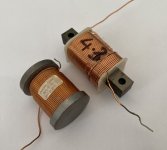
It's looking like I would only need about 28mH for the proposed notch, and a peak current at resonance of about 1.8 amps as in my previous post. Would an EI laminated core of that size be able to carry that sort of current without saturation/distortion ?I'm buying wire and wind my own coils. Copper wire costs 10euros/kg so that's cheap. For testing i've reused burned (that's why the plastic former is a bit deformed) regular EI transformer core. I wound 54mH with 0.6mm wire by hand on transformer core by mistake. I had to unwind three layers to get to 16mH that i needed. Dip the plastic former in laquer and voila. PS i don't have large hands.
View attachment 856073 View attachment 856074
Did you perform any high power level distortion measurements of your notch to make sure it wasn't saturating ?
Some cores saturate a lot easier than you'd think - in my previous 2 way (which is only rated at about 15-30 watts) the baffle step coil - about 4mH, which carries all the bass current was originally a reasonably large permite core which was claimed to be suitable for the application, however I was easily able to hear saturation (midrange break through) on certain kinds of bass transients. I swapped it for a laminated I core inductor of a very similar size and the saturation is gone.
Would a bipolar electrolytic not have been better in this application ? Did you measure the ESR of your configuration ?For caps use two 100V polarized elcos connected back to back like this --|(--)|-- it's a notch filter at 80Hz anyways. Notch such as this is working for few years now in Kef R300's i reworked and with a guy who is not being gentle to them (he listens his music with lots of bass very loud). Works like a charm.
Are you referring to the series inductors or the one in the notch ?I seem to have come up with three observations. Firstly, the inductor resistance seems to be a useful tool both in terms of the resonance and the sensitivity.
Yes, this impedance transformer effect operates over quite a wide range of frequencies, from approx 40Hz to over 150Hz in this filter. This is because the 4th order filter is effectively two series tuned resonators with resistive damping (the speaker) connected at the centre point of the second one.Secondly, in this example I'm using a 10 ohm parallel resistor and the impedance still shows as being above 5 ohms. In fact reducing this resistance will in some circumstances at some frequencies actually increase the impedance as a result of reducing the phase angle of the filter load, if you look close enough.
If the speaker impedance is too high (at the driver resonance) this reduces the damping at that point and therefore the current drawn from the source increases. (And the voltage output increases above unity)
A 10 ohm paralel resistor not part of a notch wouldn't be very feasible though as the power dissipation is high right through the entire bass region.
Unfortunately 71Hz is already a room mode in my room that needs notching out.The other thing, if I were to do this again is to reduce the target sensitivity to the level at 110Hz, and let the 70Hz peak ride because not only is it a place where such a peak can be tolerated, it is also workable with the room.
The main room modes in my room are 41Hz, 71Hz and 106Hz. All are between 4-6dB peaks, so I don't want to add another 4 dB at 70-80Hz.
When I tried to do mine as a 2nd order as a test I found the same problem - due to having to "twist" the response to include the baffle step correction I wasn't able to get a close match to the target curve, giving either a peak, or the roll off not being correct. With the 4th order it is possible to get an accurate match to the target curve as you have two more degrees of freedom to adjust.I have been working on a similar problem with a ongoing project (second order filter though), and went with impedance flattening LCR of the woofer resonance, and series resistance on the cap to gnd just like in the previous example, that made it a lot better, but it's still peaking a little bit compared to the raw driver response, because I had to 'twist' the phase a little to match with the mid.
You make a good point about the coil resistance in a notch filter where you need added resistance anyway to meat the target curve.For the impedance correction air wound coils with thin wire are not that expensive, in my case the resistance of the coils (needed two) matched the needed resistance. I got Jantzen coils from here: Kamm Lautsprecher Internet-Shop
My previous design had two notch filters in the upper midrange and I was able to make the coils a lot smaller than they otherwise would have been by exploiting the fact that I needed several ohms resistance anyway. So the coils provided a couple of ohms of the total required R and were much smaller than a similar coil with say 0.3 ohms resistance.
This can be done to some degree for this bass notch, however I'd have to be careful that the coil's R is not too high, otherwise its power dissipation could become quite high given the low Q (therefore wide bandwidth) and high power levels at bass frequencies compared to my previous upper midrange notches where the power levels are low.
So it would be a matter of balancing the total power disipation between the resistor and coil in a sensible way given their relative thermal ratings.
Last edited:
Series.Are you referring to the series inductors or the one in the notch ?
I don't usually concern about such coincidences where you plan to deal with each issue anyway.Unfortunately 71Hz is already a room mode in my room that needs notching out.
So about that, each issue is likely to respond to minimum phase filtration. Maybe even at the same time should the circumstances arise. Is global EQ out of the question? Of course speaker level will give you the lowest inductor values, low frequency line level inductors could be found in power transformers etc, if you can measure their self resonance. Or use a non inductor style of EQ.
There are alternatives, box alignment is one.
EDIT: I see that you have found a way.
Would an EI laminated core of that size be able to carry that sort of current without saturation/distortion ?
Did you perform any high power level distortion measurements of your notch to make sure it wasn't saturating ?
I've measured distortion with few types of core. Here are the results:
Influence of inductor types on distortion performance
These EI cores tested aren't the ones i winded but i've bought them locally. They failed the distortion test miserably so i won't be buying them anymore. Bad alloy i guess. It would be nice to know what type of alloy is used by Mundorf in their EI coils.
Bottom line, getting the right core could be a problem. I would advise to use ERSE i-core inductors (they're cheap) and use your own wire. Kef R300 use ferrite coils in their notch (22mH) and in series with woofer (2.2mH). Their cores behave well in distortion tests.
Some cores saturate a lot easier than you'd think - in my previous 2 way (which is only rated at about 15-30 watts) the baffle step coil - about 4mH, which carries all the bass current was originally a reasonably large permite core which was claimed to be suitable for the application, however I was easily able to hear saturation (midrange break through) on certain kinds of bass transients. I swapped it for a laminated I core inductor of a very similar size and the saturation is gone.
I'd use Dayton or ERSE I core for that. I don't know what exactly causes the distortion in core material but here are few tests:
YouTube
YouTube
....Would a bipolar electrolytic not have been better in this application ? Did you measure the ESR of your configuration ?
ESR and ESL of capacitor in series RLC is practically irrelevant. You are adding 28mH and few ohms in series with that capacitor.
Last edited:
Unfortunately 71Hz is already a room mode in my room that needs notching out.
The main room modes in my room are 41Hz, 71Hz and 106Hz. All are between 4-6dB peaks, so I don't want to add another 4 dB at 70-80Hz.
How're you notching those? Could the impedance-related peak be treated similarly?
IIRC, in a couple of his bigger 3-way designs Troels implemented a plate amp for the LF driver, and set it up to accept speaker-level inputs. ie, still usable with a standard 2-ch HiFi amp.
Apart from doing that, it looks to me like a big LCR network is going to be the only way to fix this one. You could use an air-cored inductor and build most of the series R into it. More wire, though.
Chris
OK understand on the why, but it if gets too much, you could go hybrid (it's what I did) I used (analogue) active for the woofer to mid crossover, and passive on mid to tweeter. Then you only need four channels of amplification rather than six...
The way my active crossover works, you design as if you were doing passive. I really should do a more accessible version of it using opamps for the buffers rather than B1's. I think one channel uses 8 jfets...
Tony.
The way my active crossover works, you design as if you were doing passive. I really should do a more accessible version of it using opamps for the buffers rather than B1's. I think one channel uses 8 jfets...
Tony.
Interesting. I'm far from an expert with magnetic cores and still have a lot to learn, however in my experiences so far I've found ferrite cores to be the worst (for inductance value per physical size) for bass low pass filters, and have previously had to replace ferrite cores with laminated steel types due to saturation.I've measured distortion with few types of core. Here are the results:
Influence of inductor types on distortion performance
These EI cores tested aren't the ones i winded but i've bought them locally. They failed the distortion test miserably so i won't be buying them anymore. Bad alloy i guess. It would be nice to know what type of alloy is used by Mundorf in their EI coils.
Bottom line, getting the right core could be a problem. I would advise to use ERSE i-core inductors (they're cheap) and use your own wire. Kef R300 use ferrite coils in their notch (22mH) and in series with woofer (2.2mH). Their cores behave well in distortion tests.
Ferrite types in my experience are good for high frequencies but just can't handle the low frequency high current bass seen in the series coil(s) in a woofer low pass filter without saturation on transient bass. This satuartion causes midrange breakthough since at the moment of saturation the inductance value drops dramatically, effecively inceasing the crossover frequency several octaves. How audible this is also depends on the high frequency response of the woofer - if the woofer is good to over 1Khz as the Visaton are (or in the case of a 2 way midbass) then it can be very audible as a sort of plopping noise. If the woofer has very limited high frequency response it might go unnoticed.
In my last 2 way design I orignally used Jantzen "Permite" core 3.3mH inductors for the series coil for baffle step correction (shunted with 6.2 ohms) and even though the speaker as a whole is only rated to about 15-30 watts, I could hear obvious breakthrough of the midrange with bass peaks that would have been under 30 watts.
Interesting that they claim "permite" (which I presume is just a proprietary ferrite mixture) performs better than ferrite for bass:
Jantzen Iron Core Coil with Discs | Hifi Collective
Quote: "The Permite material provides significant lower hysteresis compared to coils with ferrite cores, at the same time delivering higher power handling than the ferrite ones. Power handling 400 watts RMS."
In this case, not so much!
I have a bunch of 5.6mH laminated steel I-core inductors I've had for years so took a few turns off them to get the value I wanted (which ended up being about 4.3mH) and substitued those and there is zero audible saturation on bass even when I push the speakers themselves to their limits - the midrange remains clean. As you can see the overall size isn't particularly different:I don't know what brand they are, I bought them about 15 years ago when I lived in New Zealand. I have a vague recollection that I bought them from Jaycar but I can't be sure.
I also used a pair of these same coils with my Visaton woofers back when they used to be in closed boxes with active equalisation with a 100w amplifier - again, ferrite cores easily saturated on the bass (especially with the low frequency boost needed for the small closed box) but these laminated steel cores were absolutely fine right up to 100w with no audible saturation.
Core type really does make a difference.
A lot of factors affect core saturation. I read up on it many years ago but I'm very rusty now so I might need correcting but in general:
Ferrite is has low losses at high frequencies as it doesn't suffer from eddy currents, since ferrite is non-conductive as you have conductive metal particles suspended in a non-conductive base like a resin.
Ferrites are used extensively for radio frequency signals as steel cores would be unusable there.
However ferrite has a much lower saturation flux density than laminated steel, so for the same physical core size it will saturate more easily. This is particularly the case at bass frequencies.
When ferrite saturates it clips very abruptly. Think of a solid state amplifier clipping and that is what ferrite behaves like.
Laminated steel even when it does finally saturate distorts in a more progressive and benign way rather than abrupt clipping, so it would be difficult to tell it apart from the 2nd harmonic distortion generated by the woofer itself.
So it's best to use laminated steel (or air) cores at bass frequencies and ferrite/permite (or air) cores at high frequencies, with the cutover point being approx 1Khz.
Above something like 2-3Khz laminated steel starts becoming lossy, this manifests as the inductance value falling as frequency increases. A good example of this is the inductance of a woofer which if you measure it starts to deviate from a true inductance somewhere around 2-3Khz where the impedance doesn't rise as quickly as it would in a pure inductance. This is the eddy current losses in the steel pole piece of the woofer.
A laminated core can go a bit higher than a solid steel "core" like the magnet pole piece, however it still becomes lossy within the audible range so shouldn't be used on for example a tweeter crossover.
When used on a woofer at say 300Hz, the lossiness just means that the stop band above ~2Khz or so won't be attenuated as much as it should be, but if it's already >20dB down by that point it doesn't really matter, and the payoff is avoiding saturation in the bass.
As well as materials the core area obviously affects saturation - the bigger the core area the more current it can take before saturating.
But there's another factor too - for a given core size/material, the more turns you put on it and the higher the inductance becomes the easier it saturates because the flux density for a given current goes up with the number of turns.
So you could have a particular core which when wound to say 2mH performs fine without saturating, but when you add more turns to increase it to 8mH and try to pass the same bass current through it it will saturate much more easily.
The collary from that is that if you try to get too much inductance out of a small core you end up with a core that saturates really easily. If you need a bigger value you need to increase the core area as well if you want to keep saturation limits the same in terms of passed current.
In the very large inductors you wound it's likely that despite being laminated steel you simply had too many turns on the cores for their core area, as a result they saturate too easily. The solution is to wind those very large values on a bigger cross section core...
Attachments
Last edited:
Interesting. I'm far from an expert with magnetic cores and still have a lot to learn, however in my experiences so far I've found ferrite cores to be the worst (for inductance value per physical size) for bass low pass filters, and have previously had to replace ferrite cores with laminated steel types due to saturation.
Well you are more of an expert than me... very informative post. Thank you.
So you could have a particular core which when wound to say 2mH performs fine without saturating, but when you add more turns to increase it to 8mH and try to pass the same bass current through it it will saturate much more easily.
The collary from that is that if you try to get too much inductance out of a small core you end up with a core that saturates really easily. If you need a bigger value you need to increase the core area as well if you want to keep saturation limits the same in terms of passed current....
I'm guessing that alloy used has a very important role in distortion jump when using laminated core. Mundorf uses EI cores of very similar size with same 1mm wire (as were those i measured) but they don't rise the distortion of woofer.
Important thing to notice is that i've measured the distortion when using these coils in series with woofer. I'm not sure it would be measurable if we were to use those same coils in series RLC being connected parralel to woofer. Certainly something to be investigated.
Last edited:
DBMandrake, I just wonder if you are making this more difficult than it really is.
For sure your Visaton W300S-8 woofer is giving you a hard time because the Fs resonance impedance peak is so close to your crossover point. Why not take the crossover higher? A 12" bass ought to be happy enough crossing at 500Hz.
And why use any old simulator when Visaton Boxsim and its built-in optimiser will do all the heavy lifting for you?
This Celestion Ditton 44 bass filter ought to do the right things:
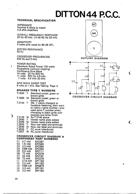
You might add the odd ohm or two to the bass shunts with film type capacitors whereas Celestion used NPE types. But why reinvent the wheel?
For sure your Visaton W300S-8 woofer is giving you a hard time because the Fs resonance impedance peak is so close to your crossover point. Why not take the crossover higher? A 12" bass ought to be happy enough crossing at 500Hz.
And why use any old simulator when Visaton Boxsim and its built-in optimiser will do all the heavy lifting for you?
This Celestion Ditton 44 bass filter ought to do the right things:
You might add the odd ohm or two to the bass shunts with film type capacitors whereas Celestion used NPE types. But why reinvent the wheel?
Last edited:
By solenoid core I assume you're just referring to the I core configuration, as it was sold as an inductor for passive crossovers, not part of an actual solenoid.Yes that solenoid core is from Jaycar. It slides, which I've used to change its value. Maybe you have some EIs lying around that will fit?
The core doesn't slide on mine - they're well and truly glued to the former although it might be possible to break it free with enough effort.
The laminations are extremely thin - much more so than on a typical power transformer with E/I cores. Thinner laminations reduce losses at high frequencies and extend the maximum working frequency. They should be useable up to about 2Khz, however I have only ever used them to crossover/rolloff at about 300Hz or so which is well within their operating range.
I spent a while reading through the following book on transformer and inductor design:I'm guessing that alloy used has a very important role in distortion jump when using laminated core. Mundorf uses EI cores of very similar size with same 1mm wire (as were those i measured) but they don't rise the distortion of woofer.
Transformer Design Handbook | Maciej Noras
Worth a look but it gets very technical and into the weeds in places, and I found a lot of the equations difficult to follow.
But there is a lot of useful info in it all the same, especially the comparisons of different core materials, and also different core topologies and winding methods.
But to sumarise some points I learnt/confirmed from it:
* Laminated steel cores support up to about 1.5 - 1.8 Tesla field strength before satuartion, one of the highest of any core type. Ferrite cores are around 0.3 - 0.5T only. So a steel laminate core of a given cross sectional area and all else being equal can handle approx 3x the power of a ferrite core before saturation - at low frequencies anyway.
* Maximum power handling of laminated steel cores falls as frequency increases. But this characteristic suits woofer low pass filters well since current is high at low frequencies where the core can tolerate high power, and lower at higher frequencies where it cannot.
* Laminated steel cores depending on laminate thickness are useable only up to about 2Khz. The thinner the laminations the better for higher frequencies. (As they reduce eddy currents) You would only use laminated steel cores in a low pass filter of a 3 way system as the low pass for a 2 way would typically be too high in frequency for them.
* All else being equal a large core cross sectional area is needed to handle higher powers, or to achieve higher inductance values with the same power handling. Adding more turns to a coil to increase the inductance increases the flux density for the same current. (brings it closer to saturation)
* There are other materials like iron powder cores which have characteristics somewhere between ferrite and laminated steel. (I wonder if Jantzen's "permite" cores are iron powder cores ? Permite seems to be a brand name used by Jantzen that doesn't show up anywhere else I can find)
* Introducing a gap, even a very small one into a complete magnetic loop, as in an EI or UI core dramaticaly drops and stabalises the permeability and greatly reduces the tendency to saturate. (But the drawback is more turns of wire are needed because the permability is reduced) This is even done with toroidal cores where they are cut in half, ground and lapped, and glued back together with a gap as small as 25 microns.
* An I core ("solenoid core", or rod core) like the laminated steel ones I have fundamentally has an air gap in the magnetic path because the flux travels through the core and then out around the coil in 3 dimensions through the air back to the other end, same as a bar magnet. This "air gap" in the magnetic path lowers permability dramatically but also dramatically reduces the tendency to saturate. The drawbacks are lower permability (more turns needed) and a poorly contained flux field - so it will be a lot more sensitive to nearby steel, other inductors etc unless oriented at right angles and spaced well apart.
It was a bit disapointing in reading that otherwise very in depth design book that I cores are basically not mentioned in any detail. As the focus of the book is primarily transformers (which almost always use closed magnetic loops) and only touches somewhat on inductors in one or two chapters I suppose that's not surprising though.
Yes, it's not entirely clear how distortion generated by the coil in shut notch filter would affect the output.Important thing to notice is that i've measured the distortion when using these coils in series with woofer. I'm not sure it would be measurable if we were to use those same coils in series RLC being connected parralel to woofer. Certainly something to be investigated.
If it generates 3rd harmonic current when saturating, the 50Hz notch would start shunting the crossover output at 150Hz, lowering the output around 150Hz but not necessarily distorting it as such.
Another way to look at it is when a core saturates the permability of the core drops back to unity (same as air) during the period of saturation (which only lasts for a portion of the AC waveform) and during that period of the waveform the inductance dramaticaly drops. This would push the frequency of the notch dramatically up in frequency, but only for a portion of the bass cycle.
This could be a very weird amplitude modulation effect, and would not manifest as regular harmonic distortion. I don't know how to calculate it, it's something I'd have to measure empirically.
Given that the notch filter would be at about 50Hz and current will fall off rapidly above and below that frequency, and it can handle high power at low frequencies, laminated steel seems to be a good option for the inductor in the notch filter provided it has an air gap, and provided it's well below saturation. An air wound coil would be infeasibly large for the value required, even though the resistance of the long length of wire could be tolerated and taken advantage of. (Many ohms of total series resistance is needed to tune the notch depth)
Last edited:
The driver itself could go that high, but it doesn't jibe with the design for many reasons.DBMandrake, I just wonder if you are making this more difficult than it really is.
For sure your Visaton W300S-8 woofer is giving you a hard time because the Fs resonance impedance peak is so close to your crossover point. Why not take the crossover higher? A 12" bass ought to be happy enough crossing at 500Hz.
Trying to operate a 12" woofer which is closely placed to the floor up to 500Hz will muddy the midrange due to insufficient time delay of the floor reflection at frequencies where our hearing doesn't hear the steady state frequency response.
The 250Hz crossver frequency is chosen for many reasons. It's the half wave spacing of the two drivers. It's the baffle step frequency of the cabinet. It's below the point where our hearing no longer hears just the steady state frequency response. It's also close to the Schroeder frequency of typical living rooms.
Also, why use an 8" widerange driver capable of bass, let alone low midrange if you're going to cut it off at 500Hz ? Complete waste. One of the tent poles of the design is to use the midrange driver over as wide a range as reasonably possible.
I'm assuming you haven't used Vituixcad 2 then ? It's not just "any old simulator"And why use any old simulator when Visaton Boxsim and its built-in optimiser will do all the heavy lifting for you?
It's probably the best free/donation-ware speaker design software/simulator available today, hands down. (My personal opinion of course)Visaton's free boxsim is a decent enough program and was a good free program back in 2013, but it hasn't been updated since, and it has since been completely surpassed by Vituixcad 2.
I've spent the last 3 years working with Vituixcad, finished a complete crossover design with it and know the program well.
I don't see anything that boxsim can do that Vituixcad 2 can't do and do better, so I don't see any reason to switch now.
I'm not sure I see the relevance of the Celestion crossover ? Different woofer, different box, (so different impedance curve) different design.This Celestion Ditton 44 bass filter ought to do the right things:
You might add the odd ohm or two to the bass shunts with film type capacitors whereas Celestion used NPE types. But why reinvent the wheel?
All I see is a woofer crossover that is a textbook 4th order filter without even a zobel network.
Trying to copy that design with a different woofer and box and without using any measurements wouldn't be any better than using a text book filter.
No offense to Celestion, but that's a pretty basic looking crossover.
Commercial speakers are usually built to a price and that typically means saving money on the crossovers which become overly simplistic filters which mean the response isn't particularly well shaped or optimised with most of the raw driver/box/diffraction annomalies showing through.
You only have to look at measurements of most commercial speakers to see very obvious but correctable flaws (like huge peaks in the presence region) that have been left in either to keep the crossover simple and economic, or because they think a bit of "zing" in the presence region is a selling factor. (B&W Nautilus 802 I'm looking at you among many others)
The truth is that if you're willing to go the extra mile in the crossover design to massage and shape the response - with a more complex filter - you can achieve dramatically better results than simplistic low/band/high pass filters and L-Pads. And if you're building a one off for yourself you don't have to worry about shaving every last cent off the per unit price like a commercial manufacturer has to to stay in business.
So there's absolutely nothing novel or useful about that Celeston crossover that could be applied to a completely different design. It's just a simple bog standard design.
Last edited:
Yes, the I cores. I've had a bunch of them. With a snug fit and a stiff enough glue they may feel like that but you know how well things stick to polypropylene.
If you grab the bobbin, mind your fingers and slam it onto a bench you might free it. Better still straddle the bobbin over supports and hit the core with a wood block.
If you grab the bobbin, mind your fingers and slam it onto a bench you might free it. Better still straddle the bobbin over supports and hit the core with a wood block.
- Status
- This old topic is closed. If you want to reopen this topic, contact a moderator using the "Report Post" button.
- Home
- Loudspeakers
- Multi-Way
- Passive woofer crossover peaking issues