You are the one to post the needed data so people can offer solutions. Frequency response (.frd) and impedance(.zma), at least.
Thanks Lojzek,
I do have all the tools I need, but I am missing a method for combining a high pass (say a large cap) with a shelving section. I am asking what the concept would look like and NOT a specific implementation that would fit my setup.
Truly yours.
Alright, can you share what is the compression driver and horn that you are interested in? I think you will get more appropriate answers to your question that way. Normally, you can start with parallel/series notch filters before/after the HP section or in any conceivable way that works in your favor. There is a schematic in Passive Crossover Designer that you may find helpful.

Yes, lets see the "crooked graph"!
The short answer to the original question is;
Yes, the functions of the High Pass filter may be combined with that of the shelving/flattening filter ( this is best employed under limited circumstances ). It can reduce component count ( usually eliminating a resistor and maybe a cap ).
- The application is most effective when the HF roll-off of the horn/driver combo approximates a straight line that slopes downwards ( with increasing frequency ).
- This approach ( of course ) also has some built-in mid-range attenuation ( choose a smaller 1st cap for more attenuation ).
Methodology ( for a 2-3 Pole filter ) ;
1st cap; choose a very small value, say 2uF - 5uF where the turnover value could be around 8 - 12K.
Coil & 2nd Cap; values are chosen to combine/interact at the waveguide/drivers natural LF rolloff ( loss of loading ) .
- As indicated by a loss of level ( going down in frequency ) and found below the peak value of the overall ( raw ) response of the Horn/Driver combo.
")
The short answer to the original question is;
Yes, the functions of the High Pass filter may be combined with that of the shelving/flattening filter ( this is best employed under limited circumstances ). It can reduce component count ( usually eliminating a resistor and maybe a cap ).
- The application is most effective when the HF roll-off of the horn/driver combo approximates a straight line that slopes downwards ( with increasing frequency ).
- This approach ( of course ) also has some built-in mid-range attenuation ( choose a smaller 1st cap for more attenuation ).
Methodology ( for a 2-3 Pole filter ) ;
1st cap; choose a very small value, say 2uF - 5uF where the turnover value could be around 8 - 12K.
Coil & 2nd Cap; values are chosen to combine/interact at the waveguide/drivers natural LF rolloff ( loss of loading ) .
- As indicated by a loss of level ( going down in frequency ) and found below the peak value of the overall ( raw ) response of the Horn/Driver combo.
Yes it is but how much sensitivity difference is there between the woofer and the CD/Horn. The more the better as you can selectively attenuate the 1-3K with a notch and by pass the attenuation with a small series cap or a series notch filter to lift the upper octaves response.
The easiest would be a simple sereis cap but Earl is correct you need to have a typical 6db per octave rool off after the mass break point of the driver. Take a look in the referenced PDF's it will give you are idea of how it can be done.
Rob
Page 7
Improvements in Monitor Loudspeaker Systems
L200B Schematic
https://manuals.harman.com/JBL/HOM/Technical Sheet/L200B ts.pdf
As one example;
Here's one compression driver/horn combo that's pretty straight-line ( in it's downward slope from 2.5K on up ) for a driver.
These traces done by Zvu ( are from the Peerless DFM-253508 on the 152i Clone from B52 .

Here's one compression driver/horn combo that's pretty straight-line ( in it's downward slope from 2.5K on up ) for a driver.
These traces done by Zvu ( are from the Peerless DFM-253508 on the 152i Clone from B52 .
Kris,
Here's an example of a filter that combines the functions of the HiPass with that of a HF Compensation Circuit ( which flattens the overall HF response ).
This is one of my Peerless drivers on a 152i Clone wavequide.
BTW; R1 + R2 are bypassed here ( iow; they are not in circuit so ignore their presence or values ) ).
- The same "out-of-circuit" observation applies to the 2 pictured PEQ circuits seen ( L4,C4,R4 + L3,C3,R3 ) . They aren't active + are not there ( functionally ).

This filter also employs a mild "Bump-Filter" ( at cut-off ) to PEQ boost a small area .
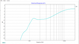
Here's a shot of the filters transfer function.
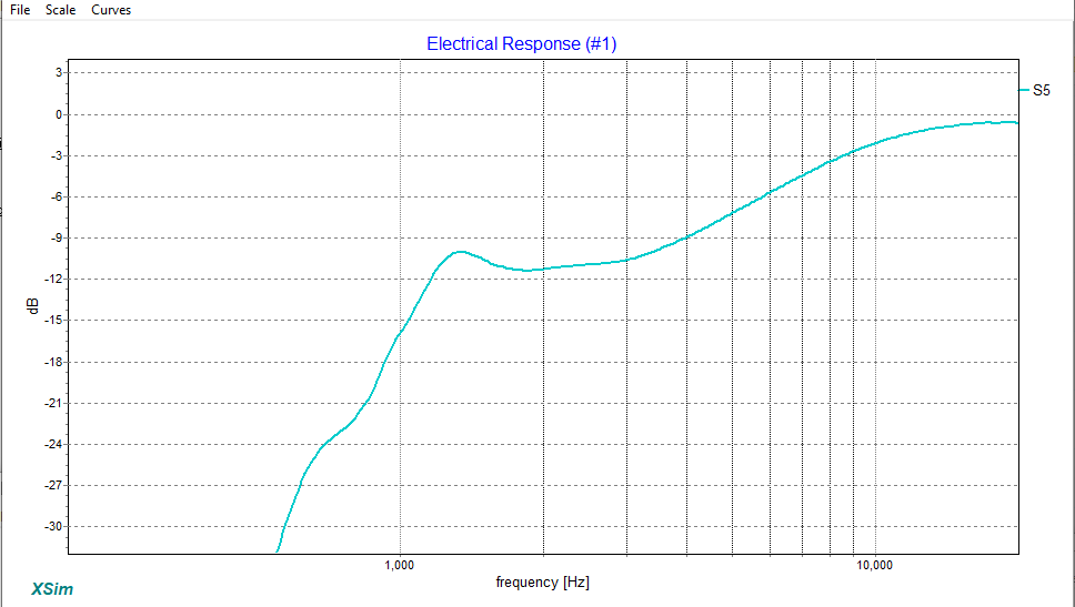
Again, this combo approach is only doable when the HF response presents a "good-enough" straight line.
These simple horn circuits are quite widely found in many Sound Reinforcement crossovers.
:
Here's an example of a filter that combines the functions of the HiPass with that of a HF Compensation Circuit ( which flattens the overall HF response ).
This is one of my Peerless drivers on a 152i Clone wavequide.
BTW; R1 + R2 are bypassed here ( iow; they are not in circuit so ignore their presence or values ) ).
- The same "out-of-circuit" observation applies to the 2 pictured PEQ circuits seen ( L4,C4,R4 + L3,C3,R3 ) . They aren't active + are not there ( functionally ).
This filter also employs a mild "Bump-Filter" ( at cut-off ) to PEQ boost a small area .
Here's a shot of the filters transfer function.
Again, this combo approach is only doable when the HF response presents a "good-enough" straight line.
These simple horn circuits are quite widely found in many Sound Reinforcement crossovers.
:
Attachments
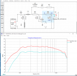
Here's a look at one way to handle the gentle roll-off curve seen in grahamgraham's trace of the Peerless driver on the STH100 waveguide.
Again, C2 is shorted and the LCR notch ( L3,C3,R3 ) isn't engaged.
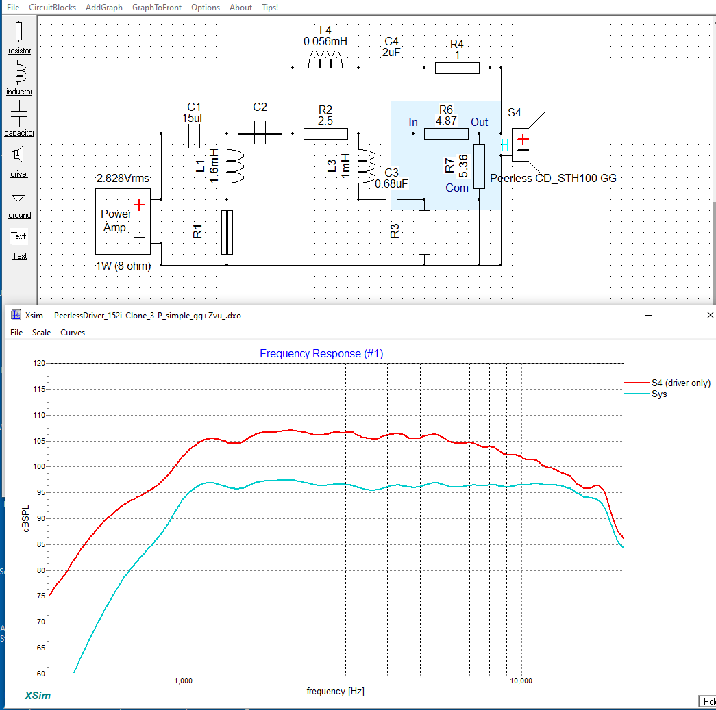
The red curve ( seen above ) is the raw response ( I've used a zma file from my own files to make this happen > so the simulation is only so-so ).
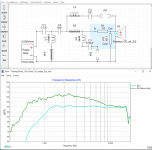
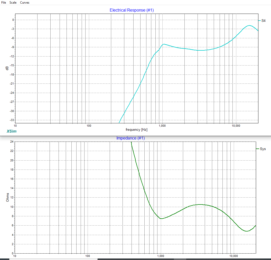
And here's what the electrical filter is actually doing along with an impedance trace.
- Both "Peaking" filters betray their presence ( when looking at the dips in the overall impedance ).
Again, C2 is shorted and the LCR notch ( L3,C3,R3 ) isn't engaged.
The red curve ( seen above ) is the raw response ( I've used a zma file from my own files to make this happen > so the simulation is only so-so ).
And here's what the electrical filter is actually doing along with an impedance trace.
- Both "Peaking" filters betray their presence ( when looking at the dips in the overall impedance ).
Attachments
- Status
- This old topic is closed. If you want to reopen this topic, contact a moderator using the "Report Post" button.
- Home
- Loudspeakers
- Multi-Way
- Combining cross overs