PL Premium is like Gorilla Glue? I hate that stuff, expands everywhere and is hard as hell to trim and sand afterward.
It doesn’t foam and ooze/expand like Gorilla glue but I think the formulation is based on similar chemistry. They both require moisture to cure. Spritzing water on the surfaces before applying makes the bond set faster. It’s incredibly sticky and messy like peanut butter when not cured. But I have found it can bond to plastics like ABS and wood better than epoxy. It’s what they use to construct commercial BB ply pro subwoofers out of.
Very cool stuff Sin Phi.
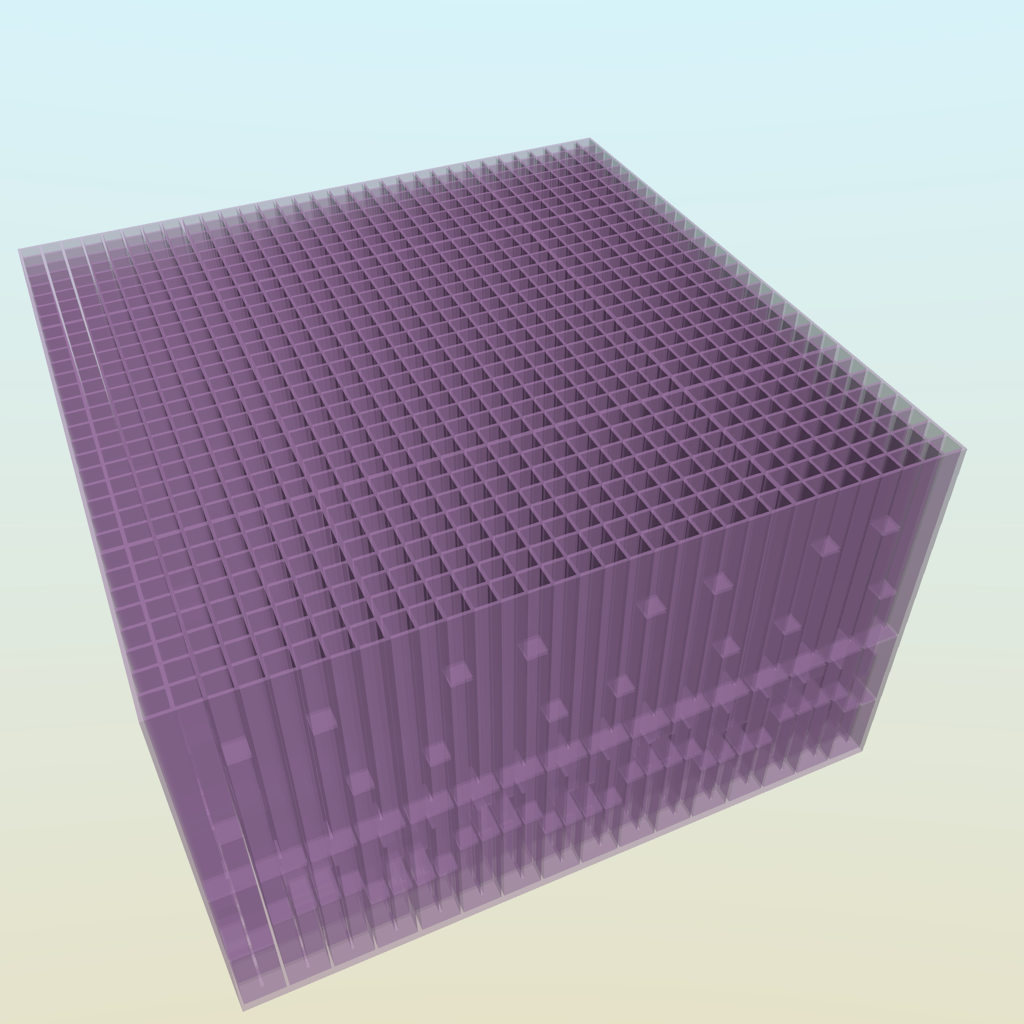
These are 1/4-wave open ended waveguides. We usually call them tuned 1/4-wave stubs. A Fabry Perot resonator is a flat-flat parallel (closed) resonator. Two parallel speaker walls would be closer to that.
But I often use these on a large scale to absorb a nasty resonance in a TL or horn loudspeaker. If the simulation in Akabak shows a peak that you can’t get rid of otherwise, I would design a thin channel of appropriate length (typically in the 15in to 30in range depending on frequency) about 1in tall and width of speaker. Stuff it progressively with fiberglass or other material. It really can knock a peak down by -6dB to -12dB. You can see this done using a 4in dia PVC pipe inside one of Danley’s tapped horn subs.
Finely printed material like this would be for very high frequencies like in a mid range or tweeter. And I have found tapered Dagger (tall 3 or 5 sided pyramid or even a round cone) rear chambers progressively stuffed to be quite effective at being an acoustic black hole for rear radiation.
Hope I'm not to late to make a couple of suggestions for testing.
1. Open cell carpet pad - cheap and readily available
2. Mass loading the top of top of the box. This would put the side walls of the box under longitudinal compression. A bag or two of concrete/ softener salt/snow melt.
Thanks for the work, very interesting read
1. Open cell carpet pad - cheap and readily available
2. Mass loading the top of top of the box. This would put the side walls of the box under longitudinal compression. A bag or two of concrete/ softener salt/snow melt.
Thanks for the work, very interesting read
Doing great work Augerpro.
Would be nice to see double .75" for the CLD panels. .25" seems to me like a racecar on donut tires.
I'm not sure many people will really want to build 1.5" thick cabinets. But here is what I've been thinking from teh results so far: CLD using the Weicon Flex 301M Classic, but with the inner box 1/4" MDF, and the outer box 1/2" MDF. My thinking is that the inner box would be braced (ultimately, not for the first measurements just so I'm not changing a bunch of variables) and so even with 1/4" MDF should be quite stiff. Then the outer 1/2" MDF leaves enough wood for final finishing of the cabinet.
I'd also be open to using 1/2" MDF for both layers. OR, 1/2" for both layers for the baffle only, where you could drill oversize holes in the outside layer, so that screws for mounting the driver would attach to the inner layer. Using a lossy gasket of some kind between the driver and baffle, this might actually isolate some vibration from the outside layer of the entire box.
Hi augerpro. Have been thinking about this. Are you sure it is a good idea to mount the SB15 unit?
I would think a lot of sound would be transmitted through it, magnitudes more/higher than from the panels/walls.
If this is the case then how will you determine what is what?
I agree.
I had a thread about exactly this a few years ago.
My thread might be worth looking at simply cos it has a jillion good links (patents and articles) in it. I moved some of the links to post 1, others are buried in the thread, e.g. post 170 shows a nice, very simple test setup that is probably a lot better than what I did.
Augerpro may remember the thread; he posted in it, and wasn't very satisfied with my methods
")
For what it is worth, see post 127 onward for my measurements - Measuring sound output from speaker cabinet walls
My take-home points from my tests and the info that people gave me were:
1) Under about 600Hz, any "box noise" (due to the back wave of the woofer)* will leak back through the woofer cone more than through the cabinet walls. It is indeed magnitudes higher.
It doesn't really matter how much stuffing you use (it has less effect the lower in frequency you go), or how rigid/heavy the woofer material is. As pictured, "box noise" leaked through the woofers even when they were obscured/loaded with about 500g of stuff.
I measured the difference with / without back EMF, and found that this only helps under ~150Hz (post 132).
Measuring sound output from speaker cabinet walls
...so there's a two octave span, between about 150Hz and 600Hz, where neither back EMF or stuffing do much to mop up this "box noise"*.
2) For good box walls, for damping and transmissability, any laminate or composite is better than any single normal material (post 104 in my thread has some examples).
3) Engineered bamboo panels are basically the best single normal material. DIY goo (resin) is better again. Cheap, too.
....so if I wanted to build to maximise this this is how I'd do (rather than use a thick panel of premium ply):
core of [anything]
--> skinned externally with 5mm bamboo
--> skinned internally with DIY goo (such as bentonite powder filled resin)
I'd also cross brace to maximise vibration --> heat via shear damping, in the manner than Dr Geddes and some of the linked patents suggest.
*Note that my test is only valid for the "back wave" - it says nothing about the vibration put into the cabinet from the woofer frame.
In Seattle, Boeing used to have a store where you could purchase all the random crap they use in airplane manufacturing.
Imagine buying 4x8 sheets of nomex honeycomb for less than the cost of MDF :O
Some marine suppliers have stuff like this. I assume it is hyper expensive.
But in California and Nevada, the only way to get foamular is in "craft" sizes of 2' x 2'. And Home Depot keeps about eight sheets onhand at any given time.
What about this stuff?
"rigid, thermal insulation board made from extruded polystyrene (XPS) foam."
Where I am (Australia) it is available in big panels, in various thicknesses, from regular hardware stores.
I've seen instructables / websites where people build kayaks etc from this foam, so it seems to be widely available, and there's plenty of info around about how to use it in DIY projects.
hollowboy> I answered Baldin's concern in my next post. There is no SB15 mounted when testing cabinet materials or bracing. That is only for lining/fill testing, and only for the one box I've set aside just for that testing.
BTW I tested both the bracing and XPS sandwich you just mentioned in this thread! I know it is a long thread with the results scattered around, so please go to my website and read a condensed version there to get up to speed.
BTW I tested both the bracing and XPS sandwich you just mentioned in this thread! I know it is a long thread with the results scattered around, so please go to my website and read a condensed version there to get up to speed.
Last edited:
"I answered Baldin's concern in my next post"
I just couldn't resist pointing out that I'd done a bit of testing on precisely this topic
"BTW I tested both the bracing and XPS sandwich you just mentioned in this thread"
I did find this info in the thread, but your site is a much better one-stop source. Thanks for that tip.
a) Nice to see more evidence that a composite of humble materials is better than a simple layer of plywood (e.g. the last graph showing plywood vs XPS + MDF).
b) Regarding your comment "I was surprised that the CLD braces didn't really seem to do much, at least in my implementation"
The old BBC tests "Factors in the design of loudspeaker cabinets - BBC R&D" gave me the impression that reducing the biggest peak is what is (audibly) important - see their comments regarding figures 8 to 11.
Your CLD braces (compared to the oak brace) seem to have done exactly that, knocking 5dB or so off the biggest spikes. By the BBC criteria, that's a victory.
Yeah but I was hoping for a lot more impact. I'm going to redo the test with 50% overlap of the braces instead of 95%.
Hi Augerpro love all your testings, but from the results obtain let me suggest working on decoupling the speaker or the front baffles with speaker from the main box. The decoupling can be done using a viscouselastic material like polyurethane arclyic adhesive. This will greatly reduced the transmission from the speaker to the cabinet above a certain frequency . CLD is effective to damp down the peaks of resonance and is temperature, thickness and material dependent for maximum effectiveness. To reduce the tranmission of airborne sound from the speaker backwave just use nornal dampers materials and add another layers of MLV or heavy Limp mass material decoupled from the main cabinet with polyester fibres etc . The MLV have to fully enclosed the interior but not touching the cabinet. It should be suspended by about an inch of damping fibres and terminated at the edge with butyl rubber.
This I think will work well from 300 to 5k hz ( midrange ). Woofer I just think making it as rigid as possible with multiple brace to push resonance above 600 to 1k hz will be fine.
I will probably be starting a new speaker built using a Kef 5 in driver from 250 hz to 20k hz using this decoupling method. Will update here if I completes the box. Cheers
Hi,Hi Augerpro love all your testings, but from the results obtain let me suggest working on decoupling the speaker or the front baffles with speaker from the main box. The decoupling can be done using a viscouselastic material like polyurethane arclyic adhesive. This will greatly reduced the transmission from the speaker to the cabinet above a certain frequency . CLD is effective to damp down the peaks of resonance and is temperature, thickness and material dependent for maximum effectiveness. To reduce the tranmission of airborne sound from the speaker backwave just use nornal dampers materials and add another layers of MLV or heavy Limp mass material decoupled from the main cabinet with polyester fibres etc . The MLV have to fully enclosed the interior but not touching the cabinet. It should be suspended by about an inch of damping fibres and terminated at the edge with butyl rubber.
This I think will work well from 300 to 5k hz ( midrange ). Woofer I just think making it as rigid as possible with multiple brace to push resonance above 600 to 1k hz will be fine.
I will probably be starting a new speaker built using a Kef 5 in driver from 250 hz to 20k hz using this decoupling method. Will update here if I completes the box. Cheers
I am curious on how you decouple the speaker driver from the speaker box. Can you describe in a little bit more detail.
Thanks.
Oon
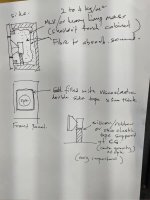
hi Onn, here is a rough sketch. I will probably not bother too much about cabinet resonace as the main coloration culprit is actually the backwave sound not absorb that gets emitted out the speaker cone . If you can fully disipate all the backwave then you will hv remove 80 to 90% of the stray sound. The box probably contributes about 10 to 20% of this. Its the first box resonace that you hv to be careful. A reasonable stiff box with a decoupled MLV or limp mass bitumen sheet that hv their resonance frequency below 100hz will be very effective in blocking the sound transmission to the cabinet. All this is good to about 200hz
The skectch is effective probably for 200hz n above.
The skectch is effective probably for 200hz n above.
Attachments
augerpro, when you are done testing boxes this way it would be very cool to see worst and best deemed enclosure far field measurements (as normal loudspeaker, without the back chamber box) if the difference is seen there. Also if there is difference to your ear. Kind of simulating real world living room scenario if the difference is meaningful or not. Better yet, if you detect a difference, try to find out which is the most practical construction method that yields sufficient results in this regard. Thanks!
Last edited:
augerpro, when you are done testing boxes this way it would be very cool to see worst and best deemed enclosure far field measurements (as normal loudspeaker, without the back chamber box) if the difference is seen there. Also if there is difference to your ear. Kind of simulating real world living room scenario if the difference is meaningful or not. Better yet, if you detect a difference, try to find out which is the most practical construction method that yields sufficient results in this regard. Thanks!
Subjective impressions would be a LONG time from now, for the simple reason that when my testing here results in some good techniques, I will be building a family of speakers using my waveguides and SB & Bliesma drivers. That is whole monster project in itself and won't be done this winter.
I'll be doing another round of testing to start separating the wheat from the chaff. This weekend I start building the new cabinets. The 1/4" MDF + Weicon adhesive CLD is most promising to me, so the next round will investigate moving to 1/2" MDF and trying another adhesive (cheaper and more available).
Also in the next round, CLD bracing with 50% overlap. CLD bracing and maybe a complete cabinet using 3M VHB tape. Box radiation (not dummy woofer radiation) when using wool batting and melamine foam lining.
I have other ideas for materials to test, but I've run out of money to purchase anything else, the above I already have on hand from the last round of testing.
I like your thinking lcwin. Also looking at the test results, from all the well performed test here the differences are not that significant I think.Hi Augerpro love all your testings, but from the results obtain let me suggest working on decoupling the speaker or the front baffles with speaker from the main box. The decoupling can be done using a viscouselastic material like polyurethane arclyic adhesive. This will greatly reduced the transmission from the speaker to the cabinet above a certain frequency . CLD is effective to damp down the peaks of resonance and is temperature, thickness and material dependent for maximum effectiveness. To reduce the tranmission of airborne sound from the speaker backwave just use nornal dampers materials and add another layers of MLV or heavy Limp mass material decoupled from the main cabinet with polyester fibres etc . The MLV have to fully enclosed the interior but not touching the cabinet. It should be suspended by about an inch of damping fibres and terminated at the edge with butyl rubber.
This I think will work well from 300 to 5k hz ( midrange ). Woofer I just think making it as rigid as possible with multiple brace to push resonance above 600 to 1k hz will be fine.
I will probably be starting a new speaker built using a Kef 5 in driver from 250 hz to 20k hz using this decoupling method. Will update here if I completes the box. Cheers
What is tricky here is also to determine and understand how much the box is actually contributing, compared to the driver output. Is it like 30-40 db lower?
To determine this you should make a big soundproof box with a hole, then place the speaker box to be tested on top playing into the soundproof box. This way you would be able to measure the backside/side output by it self, which could then be compared to the sound of the total speaker. Not an easy job, but I think necessary to split contributions.
On the other hand you could probably also just focus on the forward sound in all the test.
If the speaker plays in a normal room (should be the exact same placement in all test) you would measure the combined result, and would be able to see if there are any significant differences in the overall output. I would do distortion and freq.
From all these good test already done, I would also put my bet on minimizing the backwave.
My 2 cent
Baldin> You keep bringing up driver contribution and I've answered it several times, but you still seem confused. What you are suggesting is essentially what I have already done. Please re-read my answers or simply look at the first couple pictures at my website. There is no driver radiating outside of the box!
lcwin> have you tested this limp mass thing before? I'm skeptical that a solid sheet of anything just suspended there by fill material would really do anything? It would probably change the internal reflections of high frequencies of course, just as any solid object would, but I'm not seeing how it would absorb energy better than say, being fully stuffed with fiber material?
Hi augerpro
First of all thumbs up for all the good work you are doing here.
It's super valuable and can give a really good insight to different materials for box design.
My confusion, and I'm sorry for that, was because of some of the first pictures, both showing the small enclosure with the small driver coupled to the larger one with a SB 15 woofer mounted as well.
I for sure do not want to sound better knowing, because I'm not, and you are the one providing all the test and results. Again thanks for that.
Have reread most of the postes again, and looked at your web page.
Sorry, Yes, Sure what you do is more or less what I suggested.
One question though ... and its more because I'm a little astonished by the result:
1. In post #50 you show both box response and driver response. This shows the almost same SPL level at ca. 600 Hz. I read is as you have done the best alignment of levels you can though using 2 different distances. Good. What is a bit counter intuitive is that the level you will hear at 600 Hz is the same through the box as without box. No damping. Very interesting result, if so. Is this correctly understood?
As mentioned in post #99 by hifijim, there are different transmission ways going on with the speaker and box:
1. Structural transmission through rigid materials, that is vibrations transmitted directly to the box walls which in turn will vibrate. This is how you get sound from almost any rigid panel using an exciter Dayton Audio - Exciters . Maybe this would be an option to test the wall materials by it self. Using different materials, hanged from e.g. the roof and excited with the same level. If the 600 Hz resonance is indeed as high with as without box, I'm guessing this is the mechanism. One way to reduce this would be to decouple the driver from the box itself, with e.g. a rubber sealant or gasket or maybe decouple the whole front panel from the rest.
2. Acoustic transmission of sound pressure inside the box to the outside.
Maybe a way to test this by itself, could be to place the small speaker with it's small box, completely inside the box being tested. Paced on something soft to eliminate the direct structural transmission.
But all this is of course easier said than done in practice
3. Transmission of the back wave through the driver (SB15)
4. Maybe more ...
Again thanks for all the work you are doing. Super interesting stuff.
Kind regards Baldin
- Home
- Loudspeakers
- Multi-Way
- A Monster Construction Methods Shootout Thread