I developed a spreadsheet exactly for this reason, although I never was able to validate the empirical results from it. It does give me at least the proper order of magnitude (the electrical side of things is a bit more iffy, but to my limited knowledge seems to be somewhat useful). You can use fewer than 4 channels if you want, just set the HP/LP frequencies to appropriate values. For example, if you want to do a 2-way active, just set the bottom 2 channels (of the allowable 4 channels) to have crossover points at 20 Hz and 25 Hz, which renders them basically useless.
I've attached it as a zip file as xlsx does not seem to be a valid attachment format.
Thank you for sharing!!
I entered the values that apply to my case. It is a 4-way. Shaded yellow means values I'm not certain and need to confirm. Would you mind taking a look and sharing what conclusions you arrive at and how? I'm not sure I'm interpreting it right. Thanks in advance!
Attachments
I have just recently put together another system. The mission on this one was to be essentially a modular stack; hence a relatively small foot print.
The mid-range is a ten inch unit. It's an Altec ER-10, which, as it turns out is an exceptional unit. It is linear between 80 and 6k Hz. This pair was sourced from an older audio buddy of mine. he must have had these stored away for many years, and who ever used them before, allowed the sun to bleach out the color of one of the cones.
I am able to use it from 250-6K Hz. No cone cry and superb sound quality. Now, for the first time in many years, I can understand what all the fuss is, about that
"Altec Sound".
The ER10 is 99db/watt and I am sure I am experiencing some baffle step-loss, but it does not seem to bother me at all. While it's the same 99db/w as my big horn system was, it does not grab as much air. None-the-less, I am able to drive it with my 5 watt, single-ended, Class A, zero-feedback amplifier to very loud levels.
Hey Scott.
That's quite a departure from you large horn system.
How do the 10" Altec dispersion behave at the higher end of your use range? Common fora wisdom would suggest they would be beaming above 2kHz if not lower.
Here are a laundry list of my notes:Thank you for sharing!!
I entered the values that apply to my case. It is a 4-way. Shaded yellow means values I'm not certain and need to confirm. Would you mind taking a look and sharing what conclusions you arrive at and how? I'm not sure I'm interpreting it right. Thanks in advance!
0) Uhh... my mistake, but the dipole functionality actually isn't crippled on this sheet even though I said it was. You'll want to change cell B11 from "Dipole" to "Monopole". You will see some major differences to excursion and power requirements later on in the sheet based on this.
1) On each side, you have 1 HF driver, 1 MF driver, 2 LF drivers (wired in parallel), and 1 ELF (sub) driver?
2) Crossover points are at 70 Hz (ELF/LF), 300 Hz (LF/MF), and 1600 Hz (MF/HF)?
3) It's not critical to enter an accurate figure for the HF Sd/Xmax. It's just to give a guideline as to reasonable SPLs, but it only works well for hemispherical radiation from a standard dome/cone diaphragm. Horns and waveguides are a different beast entirely.
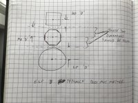
4) 'D' for the TPL-150H should be not less than (230 mm / 2) = 115 mm, where 230 mm is the height of the driver. In this context, if your HF is vertically aligned above your MF, then 'D' should be the distance from the center of the HF driver to the midpoint of the part of the baffle shared with the MF. I'll upload a sketch showing this later.
5) 'D' for the 8PE21 should be not less than (210 mm / 2) = 105 mm, where 210 mm is the flat-to-flat width of the driver (I'm assuming you will be able to properly countersink the wacky flange). Again, same comment as in 4) above.
6) 'D' for the 10G40 should be not less than (260.5 mm / 2) = 131 mm, blah blah blah (see above).
7) Once the 'D' values are updated to reflect their appropriate relative positioning on your baffle, row 30 will give you the relative driver spacing in terms of wavelengths. Depending on how far away you listen, you want to keep this between 0.5-1 (the lower the better, but the farther you sit the less critical this is for overall integration).
8) Row 32 should be pretty self-explanatory. Assuming you're confident in your Sd and Xmax values, all of these values should be greater than your target SPL @ 1 m (cell B4). The only watch-out is that you have to make sure the drivers are not thermally-limited (Pmax) before they can reach the SPL value you want.
9) I forgot to include my in-sheet comments for rows 36 and 37, which should be identical to those for rows 38 and 39. Basically, since both 36/37 have values which are less than your driver Xmaxes, you should be in good shape excursion-wise. If your driver Xmaxes were > row 36 but < row 37, you'd have to have a better understanding of the interactions.
10) Can't really help you with cell B41, I wasn't able to find any response curves for the F12. If you do find one, I would pick the sensitivity at about ~40 Hz, which to me seems to be a good middle ground for its passband. However, since it comes with its own amp, you don't really need to worry about the power supply/amplifier or even its max SPL, which is an available spec.
11) Based on the power distribution in "average" music, the required power levels are shown on row 44. That is, the HF driver needs 0.05 W, the MF needs 0.13 W, the LF (pair) need 0.23 W, and the sub needs < 1 W (after changing from "Dipole" mode to "Monopole" mode). Take all these with a grain of salt because they are highly dependent on the accuracy of the sensitivity values and also the type of music you listen to. Anything with lots of bass will require much more power and excursion in the < 150 Hz region. IGNORE row 45 since it is only for dipole calculations (sorry).
12) You can ignore B48/B49 since the F12 comes with its own amp. You wouldn't be able to change anything about that sub even if you wanted to (within reason).
13) Cell C48
14) Cell C49 looks good. It's pretty hard to get a precise value off the curve (the one I found) since the vertical divisions are so coarse.
15) Cells D48, D49, E48, and E49 look good.
16) Row 55 indicates the minimum voltage for the power supply rails (assuming it's not a single-voltage supply such as what some Class D amps use), based on when the drivers are playing a single-tone sine wave with the applied power from row 46 at the passband Zmax (that is, this is the "worst-case" voltage requirement). This does not take into account the efficiency loss of the amplifier itself.
17) Row 59 indicates the minimum voltage for the power supply rails, based on when the drivers are playing "average music". As you can see, the voltage requirements are less than when the drivers are putting all the power toward the passband Zmax, which makes sense.
18) This sheet DOES NOT account for baffle step. You'd have to manually adjust the driver sensitivity values based on the values you might get from Tolvan's Edge software, for example. With the data you entered, I suspect the baffle step would primarily impact the lower-end sensitivity/power/Xmax for the 10G40.
Questions?
Edit: sketch attached
Attachments
Last edited:
Hey Scott.
That's quite a departure from you large horn system.
How do the 10" Altec dispersion behave at the higher end of your use range? Common fora wisdom would suggest they would be beaming above 2kHz if not lower.
I certainly hope so. The horn loaded ribbon tweeter on top, also beams. A lot has been written about the importance of matching dispersion at the crossover point. From what I "hear" in this system, it is a well justified concern.
Hey, I just now thought of something I wish to share with you:
DREW'S CLUES
Scott,
Thanks so much for the link to Drew's Clues! Super interesting reading from someone with credentials. Of course, technology available for DIYers has evolved significantly in the last 20 years, but he has some very good points that will hold true forever as they are related to physics.
Point very well taken about matching xo point with directivity narrowing from the mid and directivity of the tweeter. My tweeter is Beyma TPL-150H with 80 degree dispersion. Seriously considering B&C 8PE21 as mid. A "typical" 8" would have 80 degree dispersion around 1.7kHz. B&C only publishes on-axis frequency response, so I guess testing will be in order.
A 10" mid, along the same lines, would have 80 degree dispersion at about 1.4kHz. I guess by 6kHz yours is beaming quite a bit.
BTW, I noticed Drew's setup with paper tubes for concrete as enclosure for his 10" midrange, and remembered your Tang Bands had a similar tube behind them, also lightly filled with fiberglass, yet yours were open in the back (if I recall correctly) while Drew seals the back. Did you tried it both ways and preferred it open-back?
To be quite honest, I never tried a sealed back. The reason being that my t.l. tubes are 9 inch diameter by 17 L. The 1/4 wave of that dimension sits at 200Hz, and since I need flat down to 250, that seemed to fit the bill. The TB-1772 demands a much larger enclosure, so this was my "adjustment". The TB is not really a taylor-made horn driver; it just seemed to fit my needs at the time. It has excellent tone, yet lacking in lower mid-range "bloom" when used on a conventional flat baffle; hence the horn. This system has served me well for over 5 straight years, which is a personal record. I now seek a new sound. One that is of the nth dimension. I love good horns, but this big red one is either too big, or too small, based on my new aural vision. I wish I could use my SA-8535 down to 1.3 like you will be able to run your Beyma's, but, since the my SA version uses a horn, it's just not possible. Either that, or I haven't figured out how to do it. PBN out in California used the same tweeter as mine, except he uses the flat flange version. Very wise. 8PE21 looks really, really good ! My Altec ER-10 extends up past 6 K, but now that I have been listening to this recent iteration, I don't think it's wise to push it that high. Sigh. I get listener fatigue too easy these past few days. I still marvel over the Drew Daniels approach. I'm now thinking of using a smaller tractrix horn to cover 700-6K, with the SA above it, of course. Since my deep bass system is pretty much built into the house, the only piece of the puzzle is what to do for mid-bass. I own a pair of EV-EVM-15B, and am tempted to build enclosures for those, but at my age now, nothing happens real fast.
Keep going, you're doing GREAT !!
Above all: thanks for taking the time to answer like this. Really helpful!!! 
Got it
Yes. In actuality I have two subs running summed mono, but for SPL practical purposes assuming 1 sub per side is ok.
For this calculation, yes. I'm hoping I can go higher than 1.6kHz to the tweeter, closer to 2kHz. We'll see.
OK. The AMT can take 80W and is 102 dB sensitivity...clearly not going to be the limiting factor")
Got it. Thank you.
Got it. I was measuring from inside the surround.
Good. So at 1.6kHz to the tweeter it shows 1.05. And I sit 6 feet away from each speaker. If I raise the xo point to 2kHz then D30 shows 1.31. Would that be too high for listening at 6 feet? I wonder how that would change if I moved the listening position to 7 feet.
Checked!
Good.
Looking good with the 2A3 then: 0.15W for mids and 0.05W for tweeters!
Great!
I need to look further into amp voltages in the supply rails. Have never gone there and not sure what it means for the amps I'm considering. Thanks for pointing to it!
Indeed. The baffle will be about 50cm wide (20") with 2" roundovers. The baffle step should fall in the 10G40 region.
Then I'm planning a narrowing baffle at the midranges so might get some furthe baffle step there. Need to recalc.
THANK YOU again!!
Here are a laundry list of my notes:
0) Uhh... my mistake, but the dipole functionality actually isn't crippled on this sheet even though I said it was. You'll want to change cell B11 from "Dipole" to "Monopole". You will see some major differences to excursion and power requirements later on in the sheet based on this.
Got it
1) On each side, you have 1 HF driver, 1 MF driver, 2 LF drivers (wired in parallel), and 1 ELF (sub) driver?
Yes. In actuality I have two subs running summed mono, but for SPL practical purposes assuming 1 sub per side is ok.
2) Crossover points are at 70 Hz (ELF/LF), 300 Hz (LF/MF), and 1600 Hz (MF/HF)?
For this calculation, yes. I'm hoping I can go higher than 1.6kHz to the tweeter, closer to 2kHz. We'll see.
3) It's not critical to enter an accurate figure for the HF Sd/Xmax. It's just to give a guideline as to reasonable SPLs, but it only works well for hemispherical radiation from a standard dome/cone diaphragm. Horns and waveguides are a different beast entirely.
OK. The AMT can take 80W and is 102 dB sensitivity...clearly not going to be the limiting factor
4) 'D' for the TPL-150H should be not less than (230 mm / 2) = 115 mm, where 230 mm is the height of the driver. In this context, if your HF is vertically aligned above your MF, then 'D' should be the distance from the center of the HF driver to the midpoint of the part of the baffle shared with the MF. I'll upload a sketch showing this later.
Got it. Thank you.
5) 'D' for the 8PE21 should be not less than (210 mm / 2) = 105 mm, where 210 mm is the flat-to-flat width of the driver (I'm assuming you will be able to properly countersink the wacky flange). Again, same comment as in 4) above.
6) 'D' for the 10G40 should be not less than (260.5 mm / 2) = 131 mm, blah blah blah (see above).
Got it. I was measuring from inside the surround.
7) Once the 'D' values are updated to reflect their appropriate relative positioning on your baffle, row 30 will give you the relative driver spacing in terms of wavelengths. Depending on how far away you listen, you want to keep this between 0.5-1 (the lower the better, but the farther you sit the less critical this is for overall integration).
Good. So at 1.6kHz to the tweeter it shows 1.05. And I sit 6 feet away from each speaker. If I raise the xo point to 2kHz then D30 shows 1.31. Would that be too high for listening at 6 feet? I wonder how that would change if I moved the listening position to 7 feet.
8) Row 32 should be pretty self-explanatory. Assuming you're confident in your Sd and Xmax values, all of these values should be greater than your target SPL @ 1 m (cell B4). The only watch-out is that you have to make sure the drivers are not thermally-limited (Pmax) before they can reach the SPL value you want.
Checked!
9) I forgot to include my in-sheet comments for rows 36 and 37, which should be identical to those for rows 38 and 39. Basically, since both 36/37 have values which are less than your driver Xmaxes, you should be in good shape excursion-wise. If your driver Xmaxes were > row 36 but < row 37, you'd have to have a better understanding of the interactions.
10) Can't really help you with cell B41, I wasn't able to find any response curves for the F12. If you do find one, I would pick the sensitivity at about ~40 Hz, which to me seems to be a good middle ground for its passband. However, since it comes with its own amp, you don't really need to worry about the power supply/amplifier or even its max SPL, which is an available spec.
Good.
11) Based on the power distribution in "average" music, the required power levels are shown on row 44. That is, the HF driver needs 0.05 W, the MF needs 0.13 W, the LF (pair) need 0.23 W, and the sub needs < 1 W (after changing from "Dipole" mode to "Monopole" mode). Take all these with a grain of salt because they are highly dependent on the accuracy of the sensitivity values and also the type of music you listen to. Anything with lots of bass will require much more power and excursion in the < 150 Hz region. IGNORE row 45 since it is only for dipole calculations (sorry).
Looking good with the 2A3 then: 0.15W for mids and 0.05W for tweeters!
12) You can ignore B48/B49 since the F12 comes with its own amp. You wouldn't be able to change anything about that sub even if you wanted to (within reason).
13) Cell C48
14) Cell C49 looks good. It's pretty hard to get a precise value off the curve (the one I found) since the vertical divisions are so coarse.
15) Cells D48, D49, E48, and E49 look good.
Great!
16) Row 55 indicates the minimum voltage for the power supply rails (assuming it's not a single-voltage supply such as what some Class D amps use), based on when the drivers are playing a single-tone sine wave with the applied power from row 46 at the passband Zmax (that is, this is the "worst-case" voltage requirement). This does not take into account the efficiency loss of the amplifier itself.
17) Row 59 indicates the minimum voltage for the power supply rails, based on when the drivers are playing "average music". As you can see, the voltage requirements are less than when the drivers are putting all the power toward the passband Zmax, which makes sense.
I need to look further into amp voltages in the supply rails. Have never gone there and not sure what it means for the amps I'm considering. Thanks for pointing to it!
18) This sheet DOES NOT account for baffle step. You'd have to manually adjust the driver sensitivity values based on the values you might get from Tolvan's Edge software, for example. With the data you entered, I suspect the baffle step would primarily impact the lower-end sensitivity/power/Xmax for the 10G40.
Indeed. The baffle will be about 50cm wide (20") with 2" roundovers. The baffle step should fall in the 10G40 region.
Then I'm planning a narrowing baffle at the midranges so might get some furthe baffle step there. Need to recalc.
THANK YOU again!!
Attachments
To be quite honest, I never tried a sealed back. The reason being that my t.l. tubes are 9 inch diameter by 17 L. The 1/4 wave of that dimension sits at 200Hz, and since I need flat down to 250, that seemed to fit the bill.
I have in mind trying the tube behind the midranges with lightly stuffed fiberglass like you, also fully open in the back (no tube), and also with XRK "dagger"-type enclosure. The tube is pretty simple solution so has added appeal!
8PE21 looks really, really good !
Keep going, you're doing GREAT !!
Thank you!!!
One crazy idea I've been toying with is going MTM for midrange and tweeter section, with two 8PE21 to raise sensitivity further. With such large tweeter and midranges I am likely to get lobbing. Yet I came across Goebel Divin Noblesse and Majestic which got great reviews and uses MTM with two 8" midranges and an AMT with a horn very similar to TPL-150H. Would this be a recipe for disaster?
Honestly, it's really getting into the weeds at this point unless you really can't afford any extra headroom in your amp. These power levels are so low it doesn't make sense to try to save half a watt somewhere. Last thing you'd want is to find out you only have 700 mW on your MF amp and realize you need 900 mW when you turn it up a little because someone's mowing the lawn outside.I need to look further into amp voltages in the supply rails. Have never gone there and not sure what it means for the amps I'm considering. Thanks for pointing to it!
Do the measurements based on how you actually plan to mount the drivers. If you space out your drivers a little more because you don't want the little thin strip between two driver counter-bores to be too thin, that would have to be included (if you're trying to be accurate).Got it. I was measuring from inside the surround.
These are just guidelines. It's not to say that if you're over 1, or 1.5, or whatever arbitrary number, that your satisfaction with the sound is going to drop by x amount. Theoretically, if your room is over-damped and you don't move your head at all, you could have drivers scattered throughout the room and still hear something "normal" as long as the phase and level were well-controlled right where your ears are. It's just that as this number goes up, the in-room power response is less smooth and based on the current body of literature, it seems that this is a secondary factor in perceived sound quality (primary factors include, but might not be limited to, on-axis frequency response and higher-order harmonic distortion)LewinskiH01 said:Good. So at 1.6kHz to the tweeter it shows 1.05. And I sit 6 feet away from each speaker. If I raise the xo point to 2kHz then D30 shows 1.31. Would that be too high for listening at 6 feet? I wonder how that would change if I moved the listening position to 7 feet.
I'm finding that I'm needing to make some massive overhauls to the sheet due to more and more errors I've noticed... just use it to get you in the ballpark until I'm ready to issue the corrected version.Do the measurements based on how you actually plan to mount the drivers. If you space out your drivers a little more because you don't want the little thin strip between two driver counter-bores to be too thin, that would have to be included (if you're trying to be accurate).
These are just guidelines. It's not to say that if you're over 1, or 1.5, or whatever arbitrary number, that your satisfaction with the sound is going to drop by x amount. Theoretically, if your room is over-damped and you don't move your head at all, you could have drivers scattered throughout the room and still hear something "normal" as long as the phase and level were well-controlled right where your ears are. It's just that as this number goes up, the in-room power response is less smooth and based on the current body of literature, it seems that this is a secondary factor in perceived sound quality (primary factors include, but might not be limited to, on-axis frequency response and higher-order harmonic distortion)
I'm finding that I'm needing to make some massive overhauls to the sheet due to more and more errors I've noticed... just use it to get you in the ballpark until I'm ready to issue the corrected version.
Very much appreciate the help. Directionally, it seems I would be ok. If the midrange demands 0.15 or 0.30A it's basically still ok as the 2A3 can deliver 4W and I'd like to keep it under 2W and hopefully under 1W.
Even if it took 0.3A to deliver the target 95dB SPL (cell B4), at 0.6A it would deliver 98dB, at 1.2A it would be at 101dB. Seems ok, unless I need to factor in additional 15dB for peaks and then target would turn to be 95+15=110dB and the setup wouldn't suffice.
So B4 is supposed to be RMS and the calcs account for peaks too, right? Then ball park 100dB at 1.2A would be enough, even starting from twice the current demand the spreadsheet calculated.
2 watts from a 2a3 amp will not sound the same as 2 watts from an alternate amp.
There's much more to the sound of an amp, than just "How many watts is this?"
Nothing to dispute. But could you elaborate what you mean?
Looking at Aric Audio 2A3 or Triode Lab 2A3. I realize amps have a sound signature and different people have different tastes, but wondering if this is what you meant.
Nothing to dispute. But could you elaborate what you mean?
Looking at Aric Audio 2A3 or Triode Lab 2A3. I realize amps have a sound signature and different people have different tastes, but wondering if this is what you meant.
Oh, good. I was afraid you had already purchased an amp. Over the last few years of discussing "all things audio" with you, I have noticed you tend to break things down in terms of how engineers think. Please don't take that as an insult; some of my best friends are engineers, and I have had to struggle through months, and sometimes years of patience, waiting for them to finally see (hear) the light.
All amplifiers of any decent sound quality sound different from one another, and the same exact amplifier will sound different driving one particular speaker compared to the next particular speaker.
Below the line is an excerpt from a review, and below the next line will be a link to said review.
_______________________________________________________________
Finally and most importantly, to appreciate what such an amp is capable of, you will need speakers that thrive on SET power. Sadly that's far more complex and less predictive than simply going with high efficiency. Case in point, I currently run three sets of generally SET-friendly speakers yet only one truly shows its full potential with triodes. The Zu Essence and Finalé Vivace Mini sound excellent when paired with the 2A3i but shine even brighter when associated with a FirstWatt F5 for example. The F5 is probably the most piquant FirstWatt amplifier and both speakers benefit from that slight reinforcement in the upper ranges. They also both benefit tremendously from the tighter faster bass the F5 generates. Despite radically different technologies and design briefs, both speakers share a lot in terms of sonic profile. Both can get a bit boomy when paired with a SET even on the 8Ω output. It was no different with the 2A3i which on them sounded more like a good 300B rather than an excellent 211. I will elaborate in more details in the Finalé review but to my surprise, as good as it was with tubes, this small speaker was really made for low-power solid state amplifiers like the Zu.______________________________________________________________
6moons audioreviews: Triode Lab 2A3i S
If you want them to.All amplifiers of any decent sound quality sound different from one another
No duh. Speakers can very easily sound different.Scott L said:and the same exact amplifier will sound different driving one particular speaker compared to the next particular speaker.
Oh, good. I was afraid you had already purchased an amp. Over the last few years of discussing "all things audio" with you, I have noticed you tend to break things down in terms of how engineers think. Please don't take that as an insult; some of my best friends are engineers, and I have had to struggle through months, and sometimes years of patience, waiting for them to finally see (hear) the light.
All amplifiers of any decent sound quality sound different from one another, and the same exact amplifier will sound different driving one particular speaker compared to the next particular speaker.
Below the line is an excerpt from a review, and below the next line will be a link to said review.
_______________________________________________________________
Finally and most importantly, to appreciate what such an amp is capable of, you will need speakers that thrive on SET power. Sadly that's far more complex and less predictive than simply going with high efficiency. Case in point, I currently run three sets of generally SET-friendly speakers yet only one truly shows its full potential with triodes. The Zu Essence and Finalé Vivace Mini sound excellent when paired with the 2A3i but shine even brighter when associated with a FirstWatt F5 for example. The F5 is probably the most piquant FirstWatt amplifier and both speakers benefit from that slight reinforcement in the upper ranges. They also both benefit tremendously from the tighter faster bass the F5 generates. Despite radically different technologies and design briefs, both speakers share a lot in terms of sonic profile. Both can get a bit boomy when paired with a SET even on the 8Ω output. It was no different with the 2A3i which on them sounded more like a good 300B rather than an excellent 211. I will elaborate in more details in the Finalé review but to my surprise, as good as it was with tubes, this small speaker was really made for low-power solid state amplifiers like the Zu.______________________________________________________________
6moons audioreviews: Triode Lab 2A3i S
Thanks for the link!
Indeed, I'm a recovering engineer
I realize good engineering won't guarantee perfect sound (whatever that means), but I believe will improve the odds of reaching really good sound. Keep in mind I live in Argentina, where niche electronics are non-existent and logistics to make them arrive are super complex and no practical way to return them. Hence the moves need to be carefully calculated.
Note the paragraph in the 6moons review that comes right after the one you pasted talks about damping and impedance matching as his hypothesis of what's behind the difference in sound results. Also note his observations are about parts of the frequency range (ie, "the bass was X", or "the mids were Y"). I'm looking at an active system, where these amps will only reproduce part of the band, and it's easier to match impedance and damping between driver and amp. I've been exchanging with Aric Kimball about midranges to match his 2A3 and from the ones I had short-listed he strongly recommended the 8PE21. This should increase my chances of getting really good midrange!
I am certainly not the type who is trying to "calculate sound quality" so to say. I know much can't be explained by math models. In fact, I purchased two 8PE21 and will test MTM with a TPL-150H, which the commonly accepted models say it will lobe badly - but I'd like to try out vs MT with same drivers.
This thread has made me come to the conclusion that one 8PE21 driven by 2A3 should be enough for the midrange, but MTM would provide extra headroom that would be ideal if it didn't come at the expense of other detrimental effects - such as lobbing. Time to get going with some fun action and measurements!
You're just talking about for the bass, right? Because you're planning on using tube amps with high output impedance?I'm looking at an active system, where these amps will only reproduce part of the band, and it's easier to match impedance and damping between driver and amp.
- Status
- This old topic is closed. If you want to reopen this topic, contact a moderator using the "Report Post" button.
- Home
- Loudspeakers
- Multi-Way
- Power needs across audio spectrum in active setup