Hi Erik,
The Satori is perhaps one of the best 6.5in mid bass ever made. I don’t have one, yet. It might work in this configuration - I don’t know, but I think its response might take a few more components to get as smoothly rolled off. I think the main thing about the PTT6.5 is it’s ultra low distortion - it’s similar or even better than a dedicated midrange like a class leading 10F/8424 over the 1k to 4K range, plus it has 10m Xmax. This pumps a lot more air.
PTT6.5:

Satori:
Understood, thanks for explaining!
And it is correct that you use a 2nd order xover which combined with the natural rolloff off the Purifi makes for the 4th order acoustical slope needed for the Harsch XO? The Satori does not have the natural rolloff, so would need an actual 4th order electrical xover?
It looks as if the Purifi does indeed fit as a glove in this design!
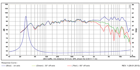
Re the RS180P, the 2KHz 3rd harmonic is a product of the unsuppressed 6KHz breakup. The behaviour in this sense is more or less the same as you find in most rigid-cone drivers. If you cross sufficiently low and steep to shunt that breakup low enough (a simple notch is rarely sufficient to get rid of the distortion amplification products) you'll find it will go away. There isn't a hard & fast rule for what is sufficient -depends on the degree of the breakup and the baseline distortion level of the driver, but think minimum -36dB suppression, preferably -48dB or more.
Right. Either that or it's purely used as a compact woofer crossing low. As always, name your poison. ") In this case, you've got a 4th order Butterworth low pass though, so speaking purely in the abstract, assuming you've got a tweeter / waveguide combination that can handle a low XO frequency with that relatively shallow slope, you should be able to cross sufficiently low to hammer it out of the way, albeit probably at the price of a couple of extra components relative to the current design here (nice job BTW).
In this case, you've got a 4th order Butterworth low pass though, so speaking purely in the abstract, assuming you've got a tweeter / waveguide combination that can handle a low XO frequency with that relatively shallow slope, you should be able to cross sufficiently low to hammer it out of the way, albeit probably at the price of a couple of extra components relative to the current design here (nice job BTW).
In this case, you've got a 4th order Butterworth low pass though, so speaking purely in the abstract, assuming you've got a tweeter / waveguide combination that can handle a low XO frequency with that relatively shallow slope, you should be able to cross sufficiently low to hammer it out of the way, albeit probably at the price of a couple of extra components relative to the current design here (nice job BTW).
Last edited:
I have wondered many times whether Samuel is aware of how popular his proposal has become. I don't think that he is a member here (yet). Apart from that there are some very cool French audio forums that he might probably be frequenting. Should contact him again since a long time already.
Regards
Charles
Regards
Charles
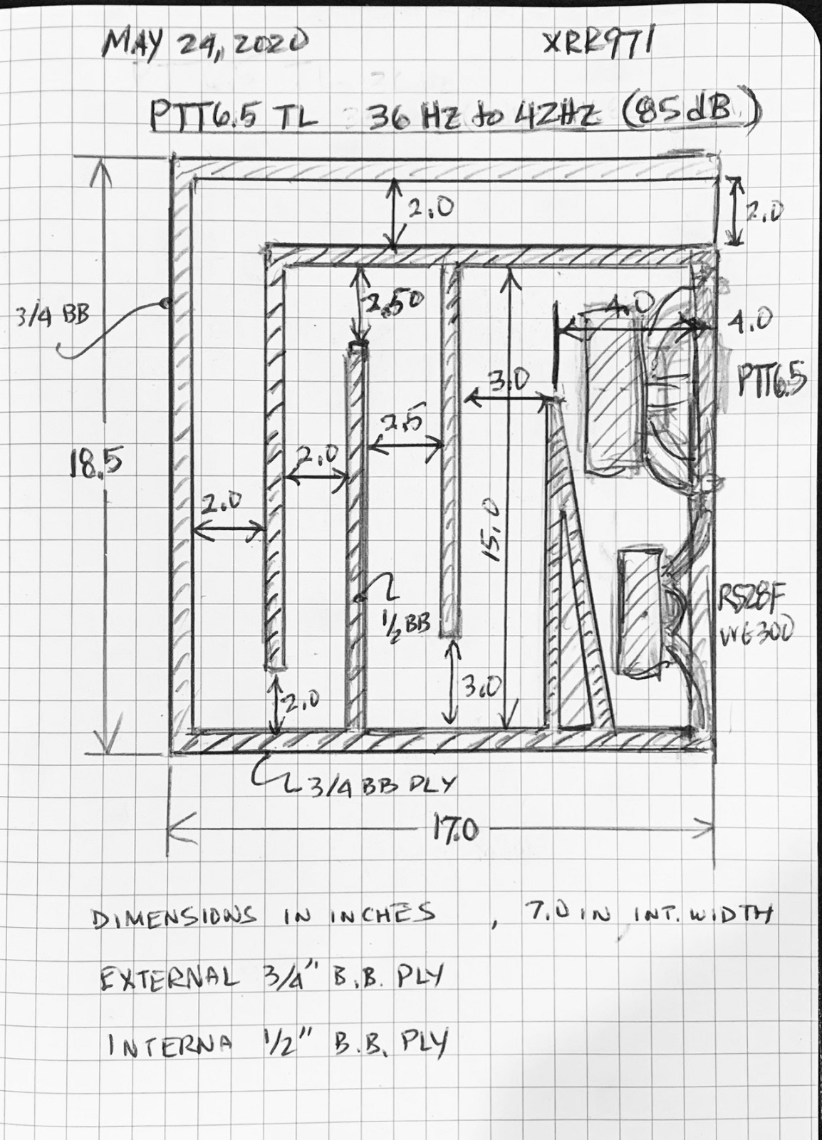
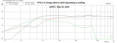
TL Design
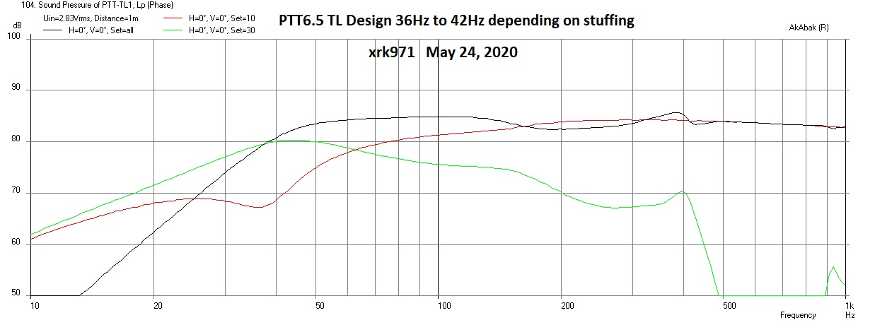
Here is the TL that I just came up with and simulated in Akabak. I am trying to keep it as a fairly compact standmount studio monitor rather than a floorstander. The design achieves between 36Hz and 42Hz -3dB depending on degree of stuffing/damping. Nominal sensitivity is 84.8dB at 2.83v ad 1m. Constructed of 3/4in BB ply on exterior panels and 1/2in BB ply on interior divider panels, box is 18.5in tall x 17.0in deep x 8.5in wide. Internal TL width is 7.0in.
Akabak predicted SPL for 2.83vs and 1m:
Attachments
You are simulating in AkABAK now I'm jealous lol...I've watched a few videos (I've made a simple box and driver using a video tutorial), I think I can get close, I 'm sure If I understand how to place the driver. How do you feel about making a step by step for the process, while you attempt to model this as a TL?
One of the things I've learned from the modelling I've done is that the only way to keep great midrange at higher volumes not just a low relative volume, is to have sub bass and midrange on different drivers...Intermodulation distortion is a function of displacement, so when a two way is played loud enough, sub bass will displace the woofer far enough to create IMD in the midrange. These new woofers would be great as subwoofers with their ability to be displaced greatly without the harmonic distortion, since sub bass is about moving air, and I imagine that the box is small...3 ways have lower displacement within the midrange than MTM's even...Just something to consider.
Also to add to your idea tank, don't forget about the practice of low tuning a BR design...When I posted about it, I explained it in the terms of tuning like a horn, 1/2 the frequency of desired system cutoff, I came across a guy who tuned his woofers to about 23hz and used two woofers....the way he designed it, the second woofer drove down group delay around resonance, he was happy with it.
Last edited:
Akabak tutorial is a bit OT.
Look for stuff by member Don Hills. He is the one who turned me on to Akabak, and everything I learned I got from his tutorials and sample scripts. It truly is powerful and can model almost anything. But a steep learning curve - well worth it once you master the basics. Very similar to high level language like any programming language. But filled with audio specific things that make modeling speakers a snap.
Akabak Simulator
This one script of how to model a Cornu back loaded horn can be used as the basis to model any TL. The trick with typical TL is to model the turns as 45deg expansions followed by 45deg contractions as a “waveguide” element.
Download the software (you will need a WinXP emulator) and read the manual and try some sample code.
Start with a sealed box, then a bass reflex, then DCR, then a straight MLTL, then a tapped horn, then a 2 way with arbitrary driver placement and a XO, then the final crown of achievement would be a 3 way Synergy.
I still can’t model a compression driver ab-initio yet. However, I did model a Karson K-15 from scratch.
Compression driver throats: That’s for gonzo modelers.
Search for keywords “Akabak tapped horn” or “Akabak TL”. You will get lots of hits.
Look for stuff by member Don Hills. He is the one who turned me on to Akabak, and everything I learned I got from his tutorials and sample scripts. It truly is powerful and can model almost anything. But a steep learning curve - well worth it once you master the basics. Very similar to high level language like any programming language. But filled with audio specific things that make modeling speakers a snap.
Akabak Simulator
This one script of how to model a Cornu back loaded horn can be used as the basis to model any TL. The trick with typical TL is to model the turns as 45deg expansions followed by 45deg contractions as a “waveguide” element.
Download the software (you will need a WinXP emulator) and read the manual and try some sample code.
Start with a sealed box, then a bass reflex, then DCR, then a straight MLTL, then a tapped horn, then a 2 way with arbitrary driver placement and a XO, then the final crown of achievement would be a 3 way Synergy.
I still can’t model a compression driver ab-initio yet.
However, I did model a Karson K-15 from scratch. Compression driver throats: That’s for gonzo modelers.
Search for keywords “Akabak tapped horn” or “Akabak TL”. You will get lots of hits.
Last edited:
Tweaking the TL design just a bit and decreasing the final height of the terminus from 2.0in to 1.5in x 7.0in wide. This drops the sensitivity from 84.8dB to 83.8dB but gives the bottom end a little more reach with -3dB point squarely at 37Hz. Cabinet height decreases to 18in vs 18.5in.
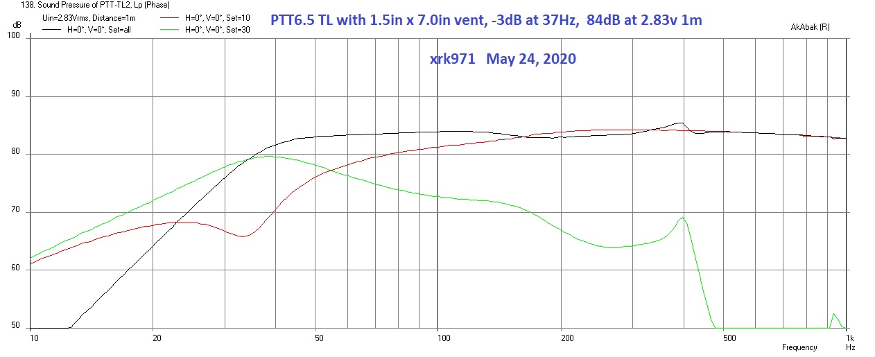
17in deep x 18in tall cabinet is a very reasonable size for a tapered TL design with 37Hz F3. Should be good for 101dB at Xmax of 10mm at 21Vrms, which corresponds to 120Wrms (this exceeds sustained rms power by 20w), so we are thermal limited not excursion limited. For temporary dynamic peaks, Xdamage of 14.5mm gives 104.5dB max SPL at 30.3Vrms with 250w peak power. Maximum air velocity at vent terminus is 16.2m/s at 104dB and 30.3Vrms, and 11.2m/s at 101dB and 21.0Vrms. And as you would expect, max air velocity is at 37Hz, falling off quickly from there so no chuffing for all but the lowest frequencies. It would be good to use a -12dB/oct high pass filter at 30Hz to prevent over-excursion from infrasonic content if playing at very high SPL's.
17in deep x 18in tall cabinet is a very reasonable size for a tapered TL design with 37Hz F3. Should be good for 101dB at Xmax of 10mm at 21Vrms, which corresponds to 120Wrms (this exceeds sustained rms power by 20w), so we are thermal limited not excursion limited. For temporary dynamic peaks, Xdamage of 14.5mm gives 104.5dB max SPL at 30.3Vrms with 250w peak power. Maximum air velocity at vent terminus is 16.2m/s at 104dB and 30.3Vrms, and 11.2m/s at 101dB and 21.0Vrms. And as you would expect, max air velocity is at 37Hz, falling off quickly from there so no chuffing for all but the lowest frequencies. It would be good to use a -12dB/oct high pass filter at 30Hz to prevent over-excursion from infrasonic content if playing at very high SPL's.
Attachments
Last edited:
Thanks, Zman01. I have also just found out that my cabinet maker who made my last TL's will do these for me as well - he won't be able to start until mid-June though. I still want to make a foamcore/XPS/cardboard pathfinder to test before he starts cutting wood though so I have some time. The RS28F-4 is now replaced by RST28F-4. I wonder if the tweeter is a drop in replacement for the old one?
I am trying to approximate a taper with successive straight sections. The drawing showing a 2in terminus is going to be smaller at 1.5in so each section is getting smaller. The damping takes care of the ripple. The Akabak simulation is pretty accurate and output is quite ripple free as my last two tapered TL’s have proven.
10F/8424 & RS225-8 FAST / WAW Ref Monitor
Low-Cost PMC-inspired TL Monitor with DC130A and DC28F
10F/8424 & RS225-8 FAST / WAW Ref Monitor
Low-Cost PMC-inspired TL Monitor with DC130A and DC28F


Hi Mainframe,
Looks like you nailed the Harsch XO on your miniDSP.
The indicators are: phase is flat with a 55deg wide band bump to the right of XO point; the combined curve is a little less than the woofer curve to the left of thr XO point; finally, the step response looks great as it looks like a right triangle.
Nicely done! How does it sound?
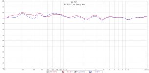
Real XO on PCB
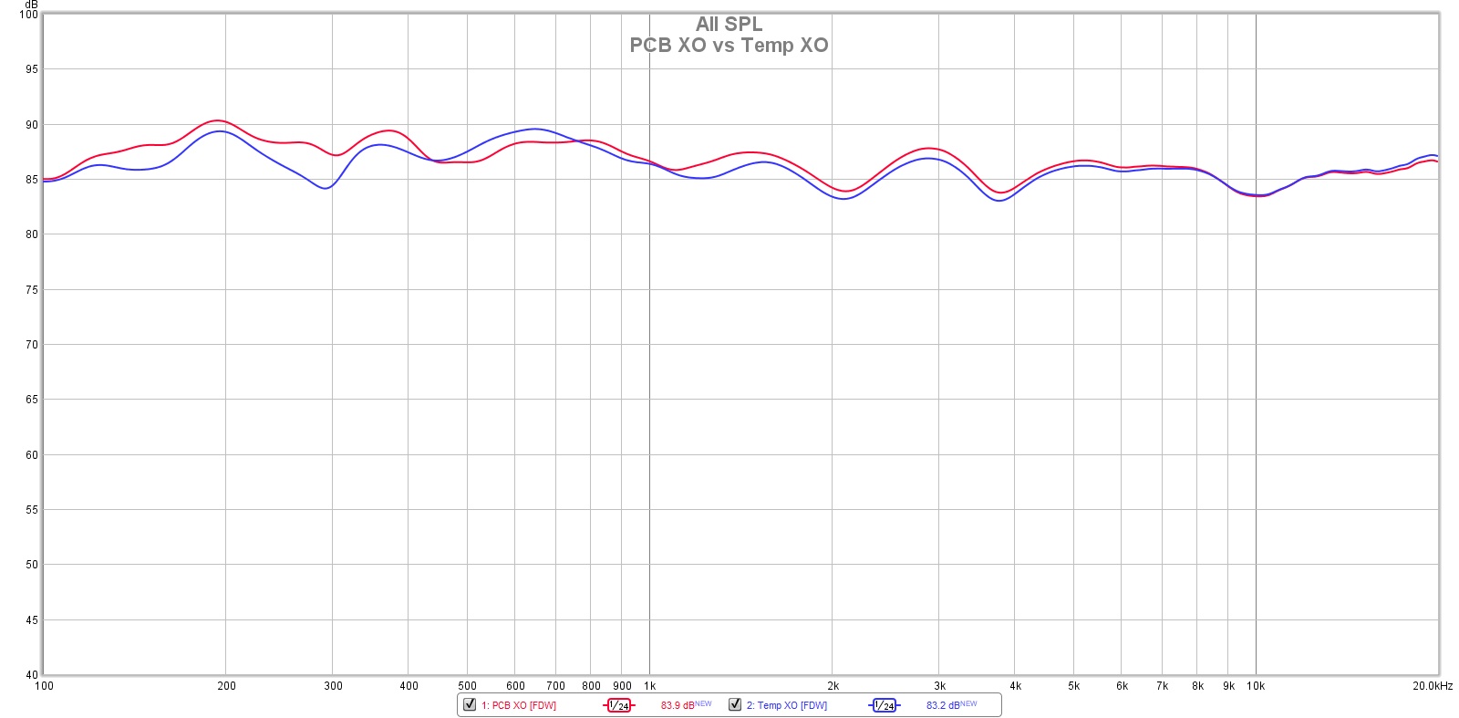
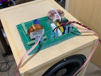
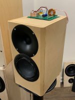
I just got my parts in for the real XO and built it up using my 10F/RS225 FAST transient perfect XO PCB. Plenty of room and the components are nicely held in place. First time I am using a flat copper foil inductor.
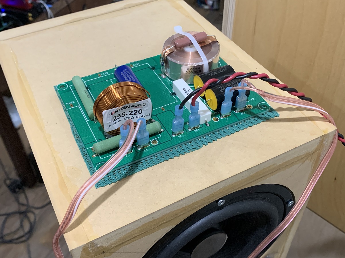

Measurement shows a little smoother in midbass, and a tad higher SPL in midbass and lower treble - probably lower DCR values.
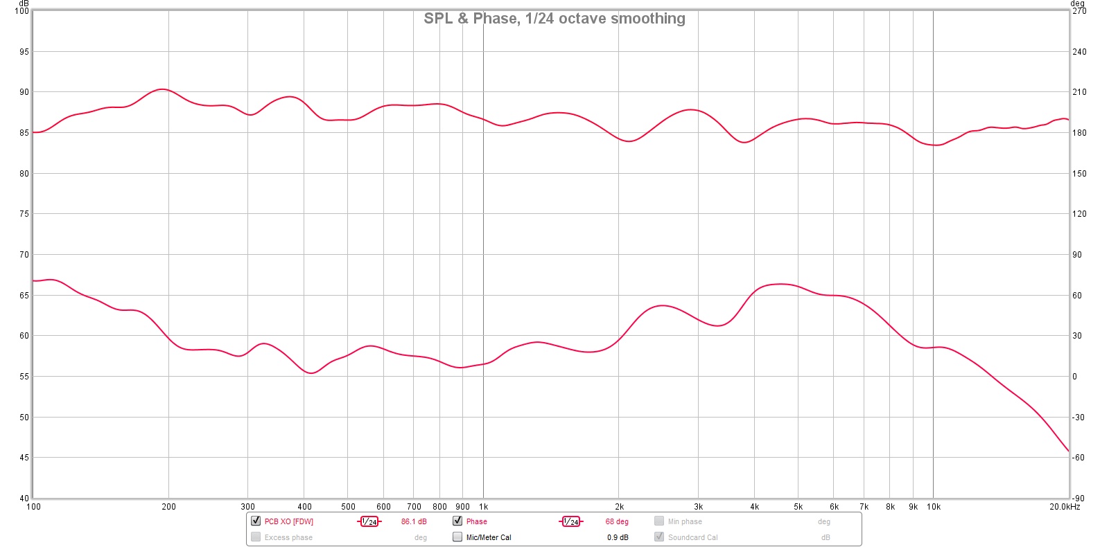
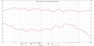
The step response and phase still looks good - the rise is exactly 55deg:
I just got my parts in for the real XO and built it up using my 10F/RS225 FAST transient perfect XO PCB. Plenty of room and the components are nicely held in place. First time I am using a flat copper foil inductor.
Measurement shows a little smoother in midbass, and a tad higher SPL in midbass and lower treble - probably lower DCR values.
The step response and phase still looks good - the rise is exactly 55deg:
Attachments
Last edited:
- Home
- Loudspeakers
- Multi-Way
- Simple Passive Harsch XO Using PTT6.5 and RS28F in a Waveguide