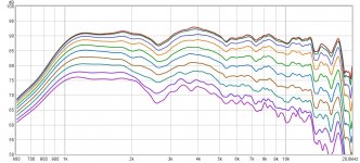
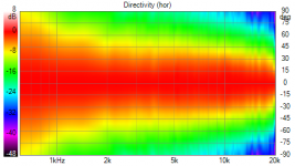
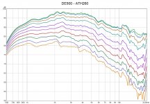
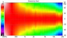
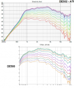
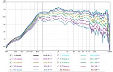
This is my first proper measurement testing Mabat's great software in a practical way. I experimented a bit with the older versions but never made proper measurements, just quick and dirty stuff") . The waveguide was designed by the master himself, it is ca 260 mm in diameter. It was measured with a Beyma CP385Nd. The dips are most probably due to improper seal between the horn and the driver, the very top end is the FR of the driver itself. I took the FR in 10° steps gated to 4 ms, no smoothing at all. The directivity map is normalized to 0° response.
. The waveguide was designed by the master himself, it is ca 260 mm in diameter. It was measured with a Beyma CP385Nd. The dips are most probably due to improper seal between the horn and the driver, the very top end is the FR of the driver itself. I took the FR in 10° steps gated to 4 ms, no smoothing at all. The directivity map is normalized to 0° response.
I think the results are just great and I think I will soon try to print the second one for some listening tests. As you can see from the pictures, even this imperfect print performs really well.
. The waveguide was designed by the master himself, it is ca 260 mm in diameter. It was measured with a Beyma CP385Nd. The dips are most probably due to improper seal between the horn and the driver, the very top end is the FR of the driver itself. I took the FR in 10° steps gated to 4 ms, no smoothing at all. The directivity map is normalized to 0° response.I think the results are just great and I think I will soon try to print the second one for some listening tests. As you can see from the pictures, even this imperfect print performs really well.
Attachments
Awesome!This is my first proper measurement testing Mabat's great software in a practical way. I experimented a bit with the older versions but never made proper measurements, just quick and dirty stuff
I think the results are just great and I think I will soon try to print the second one for some listening tests. As you can see from the pictures, even this imperfect print performs really well.
Was the print reinforced in any way before measurement? Did the print give you any problems?
I have not noticed before, you are certainly right. A little eq should help.
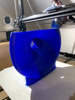
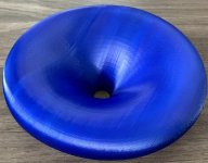
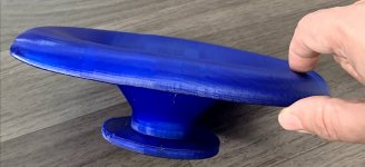
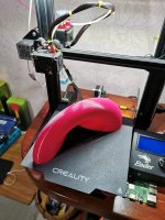
454Casull: The print finished successfully, but it was slightly deformed due to non perfect bed adhesion and warping of the plastic. Also, I had wrong setting for the supports - they were printed at maximum speed, I had an extra zero in the settings (500 mm/s instead of 50). I did nothing to the horn, even with low infill, it is quite dead - it would benefit from some damping I think.
454Casull: The print finished successfully, but it was slightly deformed due to non perfect bed adhesion and warping of the plastic. Also, I had wrong setting for the supports - they were printed at maximum speed, I had an extra zero in the settings (500 mm/s instead of 50). I did nothing to the horn, even with low infill, it is quite dead - it would benefit from some damping I think.
Hello again,
I have finally printed two TinyRs for my Linn Unik speakers, actually I have taken the file generated in the demo exported to Fusion, divided into two halves and printed in a 240mm diameter delta. The first half was made in ABS, with this material I had warping problems, I made the other halves with PETG. The result is quite correct, I have glued the parts with cyanoacrylate with activator and the joint is very good, it has resisted some fall to the ground. The first unit I taped together and put it in the unit to test, the second unit is a bit more elaborate, I have applied a coat of polyurethane primer and now wait for the finish color coat.
At the level of results I have to say that these small speakers are in my workshop of about 60 m2, the effect of the horn is a curious improvement in reproduction, from here I hope to make other prototypes with a little more previous analysis and looking for results , It has been a good test to evaluate the use of the 3d printer for the manufacture of horns.
Thanks Mabat for this awesome app
Keep in mind that you have to redesign the crossover, now that you're using a waveguide. The 'stock' Linn crossover will no longer be correct.
Or at the very least, measure the speaker and then use an equalizer to fix the response.
I found out that my printer should be able (in theory) to print the same waveguide if was scaled up to 400 mm overall diameter (from 260 mm). It would be printed in around 25 h and use a little above 1 kg of PETG filament. That makes me think about buying some 1.4" drivers
Sure, you could do that. As a result everything would just shift on the frequency axis to the left in the same ratio as the sizes. In this case it would be the ratio 1.4 - what was at 1400 Hz before will be at 1000 Hz now. This would hold for all the variables - the DI, HOM cut-ons or radiation impedance.
Keep in mind that you have to redesign the crossover, now that you're using a waveguide. The 'stock' Linn crossover will no longer be correct.
Or at the very least, measure the speaker and then use an equalizer to fix the response.
Hi,
Thanks for the note, I have a speaker with a horn and another without, I'll take the measurements, interesting
thanks
Un saludo

- Home
- Loudspeakers
- Multi-Way
- Acoustic Horn Design - The Practical Way