I would love to see more thoughts/models/sims on the Bliesma T-34B.
Probably crazy-sounding, but I have two ideas in mind- one based on the Bliesma and another with a CD/WG (Celestion Axisymmetric v other) that can XO down to ~ 300Hz to avoid the location of the crossover required for the Bliesma.
Bill
Probably crazy-sounding, but I have two ideas in mind- one based on the Bliesma and another with a CD/WG (Celestion Axisymmetric v other) that can XO down to ~ 300Hz to avoid the location of the crossover required for the Bliesma.
Bill
Off topic,
") I try to follow that idea as well with a 3" mid/tweeter to load it circa 600/800hz -and try to know if it can smoothly marry with a 15" - instead a 10"-: 3"-75mm-apex diameter wave guide for SS 10FF -
I try to follow that idea as well with a 3" mid/tweeter to load it circa 600/800hz -and try to know if it can smoothly marry with a 15" - instead a 10"-: 3"-75mm-apex diameter wave guide for SS 10FF -
But let's continue with your how to here and again thank you for the clarification effort and the huge soft work.
I try to follow that idea as well with a 3" mid/tweeter to load it circa 600/800hz -and try to know if it can smoothly marry with a 15" - instead a 10"-: 3"-75mm-apex diameter wave guide for SS 10FF -But let's continue with your how to here and again thank you for the clarification effort and the huge soft work.
Thanks, everyone. I'm pretty pleased with the result myself.
Yes, it's a Deltalite II 2512.
Compared to my previous speakers, which were about half the size (6.5in woofer and 1in dome tweeter on a 3d printed waveguide), the biggest improvements seem to be imaging precision, clarity in the midrange, and dynamic capability. The first two are almost certainly due to the improved directivity control. I'll refrain from saying more as sighted subjective impressions are known to be highly unreliable (especially coming from the guy who designed and built the things!).
It's 12in, actually. I used a compression driver partially because everyone else does. But also because the exit wavefront is a better match for the OS throat than what a dome produces. When you say "more linear" do you mean the frequency response, or the nonlinear distortion? I'm not personally convinced that either is really an audible problem in this case. The nonlinear distortion is actually quite low and the slightly rough frequency response above ~14kHz is probably not audible (I could be wrong, of course).
The woofer is an Eminence, judged by the cone and surround?
Yes, it's a Deltalite II 2512.
What's is your (initial) subjective impression of the speaker(s) in the room?
Compared to my previous speakers, which were about half the size (6.5in woofer and 1in dome tweeter on a 3d printed waveguide), the biggest improvements seem to be imaging precision, clarity in the midrange, and dynamic capability. The first two are almost certainly due to the improved directivity control. I'll refrain from saying more as sighted subjective impressions are known to be highly unreliable (especially coming from the guy who designed and built the things!
).The mid seems a 10". Why did you choose (and many diyers) a compression driver for the horned uppermid/tweeter instead a classic dome driver which can benefits of the horn reenforcment and perhaps more linear that a compressiopn driver ?
It's 12in, actually. I used a compression driver partially because everyone else does
. But also because the exit wavefront is a better match for the OS throat than what a dome produces. When you say "more linear" do you mean the frequency response, or the nonlinear distortion? I'm not personally convinced that either is really an audible problem in this case. The nonlinear distortion is actually quite low and the slightly rough frequency response above ~14kHz is probably not audible (I could be wrong, of course).BTW, what bmc0 has shown will be hard to beat because of its relative simplicity (being still an axisymmetric device), yet the performance is stellar. This is the way to go.
Thanks! For one-off designs, this method is low cost and produces highly accurate results (if you do it right
). It definitely takes some practice to get a good surface finish though.As you well know, the termination appears to be very important for getting this kind of performance from an axisymmetric device.
Last edited:
Compared to my previous speakers, which were about half the size (6.5in woofer and 1in dome tweeter on a 3d printed waveguide), the biggest improvements seem to be imaging precision, clarity in the midrange, and dynamic capability. The first two are almost certainly due to the improved directivity control. I'll refrain from saying more as sighted subjective impressions are known to be highly unreliable (especially coming from the guy who designed and built the things!
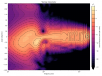
This aptly illustrates the differences between a "typical" hi-fi loudspeaker and a highly sensitive 2-way with controlled directivity.
Last edited:
I recently completed a speaker that I suppose would fit here...
Let me add my compliments to everyone else's.
That's really nice work - clever use of materials and methods, cost effective and looks excellent, what did you paint it with?
I notice that horn and woofer have been pushed closer until they intersect a little.
I assume this is to improve the polars, especially near crossover.
From your results it looks that you have been successful in this area.
I have considered this idea for a while but have only done back of envelope calculations.
Did you use some simple heuristic or rule of thumb to decide how much overlap?
Or did you try different simulations?
Best wishes
David
The paint is just acrylic latex furniture/trim paint sprayed with a cheap pneumatic gun (This one, specifically. The paint cup is pressurized, so it'll spray latex with little or no thinning). Believe me, the finish is far from perfect. You just can't really see the problems in the picture .
The driver spacing is 32cm (12.6in) and the crossover is 1050Hz, so they are about one wavelength apart. I didn't do any simulations of the complete loudspeaker, only the waveguide. Maybe I would have if ABEC3 was easier to use.
.The driver spacing is 32cm (12.6in) and the crossover is 1050Hz, so they are about one wavelength apart. I didn't do any simulations of the complete loudspeaker, only the waveguide. Maybe I would have if ABEC3 was easier to use
.
The paint is just acrylic latex furniture/trim paint
Still looks very decent.
I spray 2 pack polyurethane with a similar(ish) small set up but hate the toxicity.
I have some waterborne epoxy to try.
I didn't do any simulations of the complete loudspeaker...
Maybe I would have if ABEC3 was easier to use
Exactly how I feel, I had hoped perhaps you had done it for me
Here's the vertical contour plot, which I didn't post before...
so the nulls are narrow and have little impact on the sound power.
Thanks for the extra plot.
About as expected, for the separation and crossover slope you have.
As you say, not too much impact on sound power.
It would be nice to reduce it even further but eventually this starts to compromise the on-axis behaviour.
I'm not sure yet where the best trade-off is but think some overlap is desirable, as you have done.
Best wishes
David
Hey team.
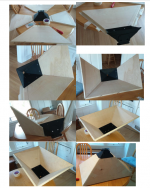
I am designing my own version of a 3D printed stubby I first saw made by bwaslo.
I am using different drivers so it's a complete redesign. I am hoping to have the plywood attached on the inside so I can simply use spacers to get the ply perfectly aligned with the 3D printed section.
So the question is, can and how do I tell ATH to transition fully from the round throat to a rectangle at 180mm up the wall, then continue (fully flattened) from 180mm to 250mm?
Hope what I am asking is clear.
Cheers
Dean
Attachments
I don't follow this part: "...continue (fully flattened) from 180mm to 250mm". Why the extra segment? Maybe a sketch would help.
I could also add an option of a true rectangle for the guiding curve, without any corner radius, if that's what you want. You would be limited to STL output but that should not be an issue if created with high enough resolution.
Without the terminating term (Term.s = 0) it could be connected to a straight-wall extension like that.
Last edited:
It's some time I have been thinking of switching to high sensitivity, plus narrow well controlled directivity speakers, following exactly bmc0's method of construction! --> building the suitable tool to shape some easy to work with material, via rotation.BTW, what bmc0 has shown will be hard to beat because of its relative simplicity (being still an axisymmetric device), yet the performance is stellar. This is the way to go.
Yet, being a complete newbie to this wave-guide thing, I am concerned with tolerances: Not sure of the precision I can achieve by such a method, so how off can you go without audibly compromising performance? Is it possible to model some slightly flawed shapes to get a general idea?
What I really need is some expert's opinion to how tolerable the flawed shape is - when does it start to be audibly flawed?
Thanks in advance, t
Last edited:
That's a good question. I don't know what precision has bmc0 achieved but it is definitely good enough. I wouldn't be too worried.
I can try to add some artificial deviations into a mesh and do some analysis altough it may be difficult to actually simulate the possible practical imperfections (that may be far from random). Also, some imperfections can even help eventually. It may be an interesting exercise.
I can try to add some artificial deviations into a mesh and do some analysis altough it may be difficult to actually simulate the possible practical imperfections (that may be far from random). Also, some imperfections can even help eventually. It may be an interesting exercise.
As long as you can make an accurate template, the result should be very good. My waveguides followed the template pretty much exactly.
I did a few simulations of minor axisymmetric defects a while ago and from what I remember, discernible differences started to show up when they were on the order of a couple tenths of a millimeter when near the throat. I doubt anyone really knows what the audibility threshold is. It would depend on the nature of the error as well.
I'd hazard a guess that if the final product is visually smooth and within a few tenths of a millimeter near the throat, there'd be little or no audible improvement with greater accuracy.
I don't follow this part: "...continue (fully flattened) from 180mm to 250mm". Why the extra segment? Maybe a sketch would help.
I could also add an option of a true rectangle for the guiding curve, without any corner radius, if that's what you want. You would be limited to STL output but that should not be an issue if created with high enough resolution.
Without the terminating term (Term.s = 0) it could be connected to a straight-wall extension like that.
Ok so I need to make sure the lower section of approx 180mm is fully transitioned from a circle to a straight sided rectangle before I can do the cutout for the ply in the second upper section.
Hope this makes it clearer.
Cheers
Attachments
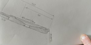
I'm still not sure I understand. Anyway, you can't make a flat wall with OS profile. It flattens with distance from the throat but is never exactly flat. There's no way how to do that with Ath at the moment. The best you could probably do is just to connect the "almost flat" OS segment to the plywood.
horn profile
Hi guys
it is nice to see some practical implementations after long theoretical thread. Kudos to mabat for excellent software tool and to bmc0 for very clever and successful design of tools and horn as well.
My plan is to made male mold from polyurethane foam on homemade lathe machine, make a layer from fiberglass and finally smoothed out as much as possible.
It is planned to make horn from fiberglass as well or maybe, from already mentioned, paper mache as described here
DIY Paper Mache Horn - The Paper Horn by Inlow Sound
To complete this I need template of WG/horn profile and even though I've red al thread it is not completely clear to me how to get it. So please little help.
What is the easiest way to get WH/horn profile in 1:1 size from all those nice software's?
regards Danijel
To sum up, following your case:
1) In your script file, enable coords output:
Output.Coords = 1
2) Execute the calculator. In the horn project directory you will find a file called *_profiles.csv
This file contains the coordinates of the profile curves (4 of them by default, all the same in a case of axisymmetric design). It is just a text file with X;Y;Z coordinates, each curve separated by a blank line.
Now you either have some other means how to process this file (can be imported into a spreadsheet etc.) or you can import these curves into Fusion 360. For Fusion you have to install the add-ins (see post #2). In Fusion you can export the curve as DXF, etc.
PS. Number of points of the curve is defined via "Mesh.DepthSegments". In general you may want to have two different settings - for ABEC output and for the CAD output.
Last edited:
- Home
- Loudspeakers
- Multi-Way
- Acoustic Horn Design - The Practical Way