Hello, I am trying to buy parts for a crossover and have a couple of questions -
L1- calls for 0.259 mH, air core #16, 0.28ohms , I'm assuming that #16 is the guage of the wire? Is 15 AWG okay to use instead?
- next question if it lists the ohms at 0.28 , can I use 0.13 ohms instead?
- - - or does the ohms resistance have to be exact , I figure it shouldn't be more resistance , but can it be less?
thank you,
So maybe an easier format ---
Question - #1. There are a lot of choices for Inductors - along with the "Perfect Lay" Inductors at Parts Express, there are Jantzen Audio coils there too. And then there are foil Inductors , and also Litz Inductors too ..... is there a best kind of Inductor?
----- Sorry for the repeat question below but I realized I asked an incomplete question way up at the beginning of this thread , it's a Newbie Mistake ....
so 2nd Question - The first Inductor L1 is for the Midrange and - is a 0.259mH , Air Core #16 , 0.28 ohms
-- The Inductor I found that I thought was close to it was a Dayton " Perfect Lay " coil -- 0.30mH , 14 AWG , 0.13 ohms ... will this work? -- (The ohms are off a little).
- 3rd Question - I think I remember reading somewhere that the larger that the thickness of the wire , the better, for less resistance? ......... But if that's not the case , I also saw 15 AWG and 18 AWG... if the Air Core 14 AWG is not close enough.
- 4th Question - Do I need to unstrap and unwind some of the wire off to get the 0.259mH from the 0.30mH coil?
-------
- 5th Question - The second Inductor I need is L2 and it is for the Woofer -- L2 is 1.106mH , Air Core #16 , 0.377 ohms
and the one I found was - a Dayton Audio "Perfect Lay" 1.5mH , 14 AWG , 0.32 ohms ..... will this one work well?
- 6th Question - Do I need to unstrap it and unwind some of the wire off the coil to get from 1.5mH to 1.106mH?
- 8th question - the ohms are 0.377 ohms and what I found was 0.32 ohms which is further off then the first Inductor L1 was ...... is this too much of a difference?
Sorry for all the simple questions this is my first crossover that I am buying parts for.
Thank you,
Best Regards,
Dean
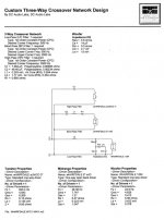
I have a question for you: what is this design that calls for 0.259 and 1.106 mH inductors? A reputable design should also have a BOM of readily available parts.
Having said that, the third digit of the decimal part for a coil doesn't make any sense, so round off to 0.26 and 1.10 or 1.11. If the design you are following really needs those values, your only option is to buy oversized coils and trim them down to the desired value. You need an LCR meter though, even a cheap one could be sufficient.
Assuming you are buying from PE, for the 0.26 mH coil I'd choose the Jantzen 0.27 mH 0.23 Ohm DCR, for the 1.11 mH coil you have 3 options: the Jantzen 1.1 mH Litz wire 0.37 Ohm DCR, the Erse 1.1 mH 0.50 Ohm DCR or the Jantzen 1.2 mH 0.33 Ohm DCR. All but the last one can be used unchanged, the last needs to be cut down to value. If you buy different inductance coils (0.3 and 1.5 mH), then you need definitely to cut them down.
Changing the DCR of a coil modifies the FR. The effect depends on where the coil is used, and how much is the difference. Small DCR differences on a primary LP coil will be unnoticeable (for example the above suggested 0.5 Ohm instead of 0.38).
Ralf
I second that!May be best to show us the circuit diagram.
Thanks all , this is helping a lot!
-- Your right I probably should have started out with the speaker and crossover ... but I was a little gun shy - Iv'e gotten a few comments about why waste my time with a very old design that doesn't probably come close to today's speakers . . .
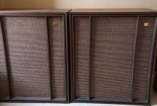
The speaker is a vintage design a Wharfedale W70 from 1966 that really shocked me as to how good it actually sounded, and that was with a very primitive xover - just a couple of capacitors and 2 L-Pads all of which are 54 years old , and at least from the L-Pads stand point are barely functioning.
-- I had read about the Wharfedale W70's , W90's and the SFB-3 speakers and I was really interested in the SFB-3 which was their answer to the Quad 57 that had just come out about that time -- ( their goal was to make a speaker that could sound as good as the quad but be much more dynamic )... so I wanted to try the SFB-3 but it's more rare and a lot more money than the other two , so I decided to go easy and try the smaller version - the W70 and that way not having to invest to much money to find out if I agreed with what people thought of the sound quality of the speaker design. So I got lucky and found a pair of the W70's locally in very good cosmetic shape for their age and only paid $200 for them. And well --- they actually really did sound very good! So along with replacing the crossover and L-Pads, I have some other ideas about how to go about taking them to the next level after that too.
--- Here is a picture of the speakers , unfortunately this is before I cleaned them up - they were very dusty and dirty. I also want to refinish them ... and maybe add new veneer too - we'll see ....")
https://i.ebayimg.com/images/g/eVYAAOSwQXZeTwJi/s-l1600.jpg
---- And here is one of the more modern but simple crossovers I want to try ---
http://www.cyberbilly.com/chicken/W70038.jpg
-- Your right I probably should have started out with the speaker and crossover ... but I was a little gun shy - Iv'e gotten a few comments about why waste my time with a very old design that doesn't probably come close to today's speakers . . .
The speaker is a vintage design a Wharfedale W70 from 1966 that really shocked me as to how good it actually sounded, and that was with a very primitive xover - just a couple of capacitors and 2 L-Pads all of which are 54 years old , and at least from the L-Pads stand point are barely functioning.
-- I had read about the Wharfedale W70's , W90's and the SFB-3 speakers and I was really interested in the SFB-3 which was their answer to the Quad 57 that had just come out about that time -- ( their goal was to make a speaker that could sound as good as the quad but be much more dynamic )... so I wanted to try the SFB-3 but it's more rare and a lot more money than the other two , so I decided to go easy and try the smaller version - the W70 and that way not having to invest to much money to find out if I agreed with what people thought of the sound quality of the speaker design. So I got lucky and found a pair of the W70's locally in very good cosmetic shape for their age and only paid $200 for them. And well --- they actually really did sound very good! So along with replacing the crossover and L-Pads, I have some other ideas about how to go about taking them to the next level after that too.
--- Here is a picture of the speakers , unfortunately this is before I cleaned them up - they were very dusty and dirty. I also want to refinish them ... and maybe add new veneer too - we'll see ....
https://i.ebayimg.com/images/g/eVYAAOSwQXZeTwJi/s-l1600.jpg
---- And here is one of the more modern but simple crossovers I want to try ---
http://www.cyberbilly.com/chicken/W70038.jpg
Last edited:
Ignore such comments, you've got a bit of loudspeaker history there!Iv'e gotten a few comments about why waste my time with a very old design that doesn't probably come close to today's speakers . . .
So, you are looking at a published, custom crossover design for the W3 - that is most helpful information.
Attachments
I fail to see why the capacitor, inductor and resistor values have to be so precise given that your loudspeaker drivers will have aged differently from those of the person who designed the custom crossover.
Choose components whose standard values are close to those listed and don't get anal about the whole sheebang!
For example, C2 could be a 47uF without affecting the result audibly.
Choose components whose standard values are close to those listed and don't get anal about the whole sheebang!
For example, C2 could be a 47uF without affecting the result audibly.
Alternatively, there's a lot to be said for renovating the crossover as it was originally designed, simply by substituting modern polypropylene capacitors.
This would preserve/enhance the vintage sound and prevent Wharfedale founder Gilbert Briggs from turning in his grave!
I believe that Wharfedale used 50 ohm potentiometers and these could usefully be replaced with modern 8 ohm variable L pad controls.
This would preserve/enhance the vintage sound and prevent Wharfedale founder Gilbert Briggs from turning in his grave!
I believe that Wharfedale used 50 ohm potentiometers and these could usefully be replaced with modern 8 ohm variable L pad controls.
- Hello, Thanks, yes I plan on first just replacing the original parts with the same values, and of coarse replacing the 4 L-Pads too... and then after living with it for a few days to get a good idea of the sound, then change it out for the new crossover to see if it makes a significant difference or not.
- one thing I'm taking in to account is that the Wharfedale W70 in it four variations is not nearly as an endangered species as the much more expensive SFB-3's are, there are a lot more of them around than there is of that top of the line model.
Best Regards,
Dean --------------
-- PS. I found a second modernized Crossover for the W70 - I'll put it in the next post, I have some medical stuff I have to do today -- I also have some more Ideas on some other Modifications I want to try on the W70 as well -------- Thanks, guys!
- Sorry for the commercial break ... Here is the second crossover ... it looks very close to the other one as far as the number of parts , but it looks like each part value is just a little different.
http://www.cyberbilly.com/chicken/W70039.jpg
http://www.cyberbilly.com/chicken/W70039.jpg

- Anyone have an opinion on which which crossover is the one they would try - is there to tell from the Thiele- Small Parameters which would be best? I'm guessing that the the difference is at what point each driver is crossed over at is the difference - it doesn't appear to this Newbie that much difference in the basic design - as in 1st, 2nd , 3rd order -- that part seems the same .
- Status
- This old topic is closed. If you want to reopen this topic, contact a moderator using the "Report Post" button.
- Home
- Loudspeakers
- Multi-Way
- Crossovers and which Inductor is right?