Hi,
Not directivity index but you could guess it:
https://www.diyaudio.com/forums/multi-way/351883-3-active-horn-speaker-monitor-4.html#post6142193
If you need smaller ( or larger size) just ask.
Not directivity index but you could guess it:
https://www.diyaudio.com/forums/multi-way/351883-3-active-horn-speaker-monitor-4.html#post6142193
If you need smaller ( or larger size) just ask.
Last edited:
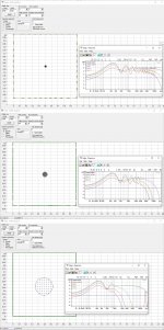
The polar maps linked are indeed the directivity behavior you can expect from 6,5" to 15".
These are approximation ( they are simulation based upon SD ( membrane surface) ).
Directivity index is used to determine a horn usually, that said you could derive it from the polar map of direct radiating driver if you want. Take a look at the thread linked, there is a link to a Jbl 2380a horn. In the datasheet you'll see directivity index. But it'll not be the usual way to plot direct radiating drivers for what i've seen.
Last edited:
Here read this also look at the overall index lots of really good info about directivity in some of the other Altec papers.
https://greatplainsaudio.com/wp-content/uploads/2017/07/TL_237.pdf
Rob")
https://greatplainsaudio.com/wp-content/uploads/2017/07/TL_237.pdf
Rob
I think DI is more appropriate when you're talking about a specific directivity, and just directivity when speaking casually. And a plot of DI vs say, the DI or a figure of DI whether talking about a single frequency or a range.Thanks for the link. I may have been using the term directivity index improperly. Maybe it's just directivity?
Here read this also look at the overall index lots of really good info about directivity in some of the other Altec papers.
https://greatplainsaudio.com/wp-content/uploads/2017/07/TL_237.pdf
Rob
It was an Altec paper! Thank you Rob, i've spent an hour looking for it believing it was from Jbl.
Some info here
https://www.klippel.de/fileadmin/_migrated/content_uploads/KLIPPEL_Sound_Radiation_Poster_01.pdf
We have wonderful freeware simulation software to study also off-axis radiation pattern of a driver and a driver in a baffle
Tolvan Data
Software
The problem with simulations is that they use flat piston model for the radiator. But that effect is smaller. Nowdays we have also freeware measurement software and cheap calibrated microphones...
- Status
- This old topic is closed. If you want to reopen this topic, contact a moderator using the "Report Post" button.
- Home
- Loudspeakers
- Multi-Way
- Directivity Index of a Driver by it's Size