Usually a blown tweeter is a symptom of something else ... and with both blown at the same time I'm pretty sure you need to be looking at your amplifier...
I had a rough time finding specs for these speakers but they appear to be rated for "80 to 250 watts"... Now what those numbers mean is that if your amp is below 80 watts per channel you are likely to overdrive your amplifier before you reach a reasonably loud SPL. If your amp is over 250 watts, you risk overheating the speaker voice coils with too much current.
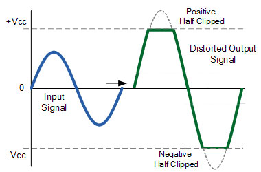
Clipping is an amplifier overdrive that, even at low frequencies, will kill your tweeters pretty quickly. The reason this happens is that the amplifier is clipping off the tops and bottoms of the musical wave form, creating something like square waves. Square waves carry a ton of harmonic content that reaches way way up into the higher frequencies... which can overheat and burn out a tweeter.
When I was doing audio service in customer's homes/studios, roughly a fifth of my calls were for blown tweeters.
The simple answer... you need more power.
Really, the solution is that you need a more powerful amplifier so that you aren't clipping it. Alternatively... turn down the volume.
I had a rough time finding specs for these speakers but they appear to be rated for "80 to 250 watts"... Now what those numbers mean is that if your amp is below 80 watts per channel you are likely to overdrive your amplifier before you reach a reasonably loud SPL. If your amp is over 250 watts, you risk overheating the speaker voice coils with too much current.
Clipping is an amplifier overdrive that, even at low frequencies, will kill your tweeters pretty quickly. The reason this happens is that the amplifier is clipping off the tops and bottoms of the musical wave form, creating something like square waves. Square waves carry a ton of harmonic content that reaches way way up into the higher frequencies... which can overheat and burn out a tweeter.
When I was doing audio service in customer's homes/studios, roughly a fifth of my calls were for blown tweeters.
The simple answer... you need more power.
Really, the solution is that you need a more powerful amplifier so that you aren't clipping it. Alternatively... turn down the volume.
Last edited:
The tweeter was made by … Foster.
Not likely. The markings are not in the Foster format. I have seen those kinds of markings but have over 2k of pictures to go thruyet to try to find simialr markings.
dave
Usually a blown tweeter is a symptom of something else ... and with both blown at the same time I'm pretty sure you need to be looking at your amplifier...
Clipping has certainy killed a lot of tweeters. We got to the point where we could swap out the tweeter in a Large Advent in less than 10 min.
dave
Clipping has certainy killed a lot of tweeters. We got to the point where we could swap out the tweeter in a Large Advent in less than 10 min.
 I was never quite that fast ...
 But yes, as I said, he probably needs either more amplifier power or less manual power on the volume knob.
The story on the failed tweeter is I am using some of my second rate components right now. Years ago I ran a h/k Citation 7.0 preamp and a Citation 7.1 amp. The amp failed two channels so has been in storage. So I was used to playing these speakers loud and clean. But for a kid friendly home I have a Parasound HCA-1000A fed via a Emotiva Umc1. It's just not the same. Got a new Creek CD player so was seeing if I could tweek some settings to get something close to the old system. I figured one tweeter wasn't performing and while mucking around with the preamp settings I accidentally hit the white noise generating "speaker calibration" function at a higher listening volume than normal and that took out the one tweeter for sure. That's the tweeter I have removed at this moment. So yes, stupidity on my part and perhaps the first failed on its old age, or the crossover, haven't looked at it yet. Plan to get the 7.1 repaired and then setup with the 7.0 in winter. It was a pretty nice system for my budget without getting exotic.
I am learning about crossovers right now. Read AllenB thread on the basics of them so getting an understanding. I'm an electrical tech so I deal with capacitance and inductance as it pertains to power system design and testing. I understand the basics but how they apply to sound is a different field of expertise. But I am understanding how I can reduce the tweeter output with a series resistor. The Veritas drawing shows a 4.7 ohm resistor in series so looks like that is the one I would change to adjust the output level. I couldn't begin to get into phasing and impedance matching though.
That said, I understand the recommendations for staying with a 1" aluminum dome tweeter and one with a rating of >90db to give me some room to adjust the series resistor. On/off axis response would seem to indicate quality of unit? Don't know.
I have emails out to solen, speaker exchange, Klipsch and a couple smaller shops to see if anyone has done any legwork already on a suitable replacement.
I may not get it exactly right with a replacement but need to understand the basics so I can get close.
Nearest city for me is Regina, Sk and I don't think there is much for services for doing crossover adjustments via testing.
Much of the stock tweeter crossover is dedicated to sharp, frequency dependent corrections specific to the original tweeter. Fortunately you may not need to recreate their effect with a well chosen modern replacement, and can possibly remove or bypass them.
Apart from that the bass is removed with an L-section filter, whose resonance damping is affected partly by the series resistor.
Apart from that the bass is removed with an L-section filter, whose resonance damping is affected partly by the series resistor.
Ok, to ensure I am thinking of this properly:
What is in blue circle I should not have to change since a similar tweeter design and size would use a similar crossover point so I likely would not be concerned with anything here.
What is in the Yellow circle is for impedance matching and therefore dependent on the tweeter ohms and impedance through frequency range. So perhaps that can be modified based on known performance of the replacement tweeter if it looks like this original design may be of concern.
The part in the red circle I don't know. I see the series resistor. The inductor/capacitor/resistor in parallel with the capacitors seem to me like a phase shifting arrangement. Is this the area that could likely be omitted? Aside from the 4.7 ohm resistor and two caps in parallel. It's a parallel circuit to the 4.7 ohm so lowers the overall circuit resistance therefore if it came to removing the inductor circuit path I would put a smaller series resistor in to start with.
Not going to try to reengineer the crossover, just want to understand the sections to know which I may need to give some attention to.
Thanks
Ken
Attachments
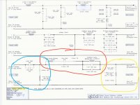
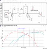
Blue ( Teal ) = the 2 Pole Hipass ( giving the 2.5K crossover point )
Yellow = a 910hz resonance trap ( notch ) that's wired across the load to attenuate the effects of the tweeters impedance peak.
Red ( there actually 3 distinct areas of interest here )
(a) 4.7 ohm resistor passes all audio above the 2.5K crossover point ( though the signal is attenuated by the resistor )
(b) ( LCR of .18mH + 1.5uF + 3.3ohms ) High Frequency Bypass ( with PEQ centered around 9700hz ) which allows a frequency dependent bypass route that skirts signal around the 4.7 ohm resistor ( effectively bumping up a specific frequency area ).
(c) The ( LC consisting of .0095mH coil paralleled to the 4.8uF cap ) is there acting as a 23.5 Khz "spike-killer" notch to reduce the effects of the typical UHF breakup that accompanies aluminum domed tweeters.
All the included parts offer powerful contouring capabilities that help match the curves of any replacement to that of the original tweeter ( IOW, they are really quite useful ).
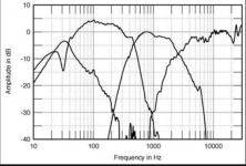
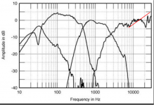
The original curves are here ( from a Stereophile review of the Energy Veritas 2.8 > which used the same mid/hi module );
I'm done tweaking HiPass reworks for 2 of 3 possible tweeters in the less than $60. range ( taken from the Solen list I provided ).
- SEAS and Peerless reworks are finished with Dayton being the next needing some attention.
I'll eventually post all three when I'm finished ( sometime over the next day or two ).
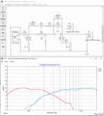
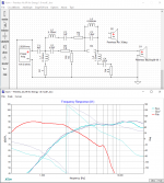
EDIT: Here's the SEAS rework;
Blue is curve of replacement SEAS tweeter ( grey in background is original )
Red is 3" midrange ( derived from Stereophile review ).
Attachments
Last edited:
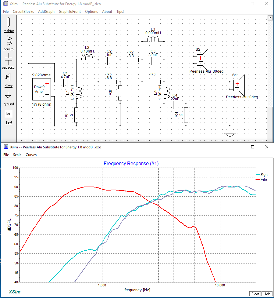
Here's another contender ( of a substitute tweeter for the Veritas 1.8 ).
This uses the Peerless da25bg0804
Tracking through the crossover region look reasonable.
This uses the Peerless da25bg0804
Tracking through the crossover region look reasonable.
Attachments
Last edited:
Here's a possibility from SB ( cost is slightly over $60. Cdn ).
It's the SB 26ADC-C000-4
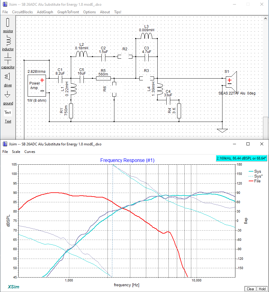
This one required the most extensive rework of the crossover > but it does have the best polars and is currently garnering some praise from users.
It's the SB 26ADC-C000-4
This one required the most extensive rework of the crossover > but it does have the best polars and is currently garnering some praise from users.
Attachments

Attachments
A revision since the 4 ohm version of the Peerless tweeter isn't currently available as a pair ( from Solen ) .
Therefore, here's the 6 ohm version of that Peerless.

FWIW, the phase tracking isn't as good as the SB version ( but then I'm only chasing imaginary lines here anyway ).
Also, like the SB I've added a 3rd pole ( capacitor ) to the HiPass to more accurately track the low-end roll-off of the original Stereophile trace.
Therefore, here's the 6 ohm version of that Peerless.
FWIW, the phase tracking isn't as good as the SB version ( but then I'm only chasing imaginary lines here anyway ).
Also, like the SB I've added a 3rd pole ( capacitor ) to the HiPass to more accurately track the low-end roll-off of the original Stereophile trace.
Attachments
Wow, this is really good, I can understand how the crossover is working now.
Solen is looking like my preferred source. Speaker Exchange would like the mf/hf assembly sent to them to supply a tweeter and install. Which is ok but I don't mind diy work.
I don't mind paying more for a tweeter. Appreciate all your work and time here guys. Earl, if I set my budget at CAN$200 ea does that help? I see Eton, Seas, Bliesna with options that extend out to 20khz with the kick up at 25 kHz. They tend to be 6 and 8 ohm units. Where as your suggested option is 4 ohm. Are you able to guesstimate the original tweeter resistance based on that 910 Hz filter (yellow circle area)? Just curious.
I can see now that these speakers need some upgrades over time. Never considered that before. The tweeters may have a finite life to them regardless if I destroy one personally. Looks like I will take the opportunity to pull the crossovers out and go through the rest of the capacitors. I can make an external crossover for the tweeter if it gets to be problematic to reuse the existing board.
One question getting back to the basics. Since it looks like I will be making a new panel to mount the mids/tweets in, how important is material chosen? I don't have a means to make the nice curves or precise hole diameters but could get parts water jetted and if so, would 1/4" aluminum or thin steel work? The water jet shop can work with other material such as micarda and glastic but have never had a need to ask them to jet wood, likely they could. Just wondering what materials are off the table for consideration.
Thanks
Ken
I don't see spending more than $ 65.00 per tweeter as being money well spent.
You're better off spending $200.00 Cdn on 2 pairs of tweeters ( IMHO ) and then wiring up both network types and choosing the one you figure sounds best.
- That education is money better spent IMO .
I'd recommend the SB Acoustics and the Tymphany Peerless 6ohm .
Its quite arguable that in a 3-way like yours, the heart and soul of the sound is dictated by the sound quality of the mid-range.
- Without hearing and evaluating the SQ of that 3" mid it's impossible to make recommendations as to what will matchup best with it // that's why I recommend starting off with tweeters in the budget price range.
Some of these tweeters have still gotten rave reviews despite their affordability.
The linked to SB tweeter has been measured by Troels Gravesen HERE! .
Wander through his site to get a feel for the good work that he does.
The insert needs to be non flexible and non resonant .
Personally, I'd be working with wood for the insert ( no matter what ).
Metal may look nice but is way too unforgiving ( when it comes to lay-up and layout time spent vs aesthetic return on effort ).
The frames of the tweeters and mids should be flush mounted ( not standing proud of the baffle board. Flush-mounting reduces diffraction effects.
You'll need the tweeters on hand ( if you are going to work with metal ) to get the cutouts exact / plus get mounting holes that actually line up.
Are you a wiz a Cad drawings ?
Spend some hours Googling these tweeter models and reading everything others have said about them.
I am learning about crossovers right now. Read AllenB thread on the basics of them so getting an understanding. I'm an electrical tech so I deal with capacitance and inductance as it pertains to power system design and testing.
The parts behave exactly the same in audio as they do anywhere else (they're not that smart
) A high pass filter is the same, a low pass is the same, band pass and band stop are the same... just with differing part values adjusted for the frequencies involved.I use XSim (Look for XSimSetup.exe in the folder) This software comes with a bit of a learning curve so at first you should take their standard amplifier and speaker and play with one component at a time... put a capacitor in series and see what it does, then a coil, then a resistor... then try low pass, high pass, bandpass and band stop... each time playing with part values so you can see what does what. From there, it's pretty easy to use.
Ok Earl, there's a first time for everything. Usually spending extra upfront can reduce cost in another area. However if there is no benefit to spending extra here then I will take the advice.
Chris at Solen did recommend the SEAS 27TBFC/G06 for similar reasons, didn't think spending extra would gain a large benefit unless going very expensive. This one was recommended on the basis that Chris figured the least amount of crossover rework would be needed. At 50 y/o what the tweeter does beyond 10 kHz is really not going to matter anyway it would seem.
Doug, to your point it is the applications that are different. Inductance is in series and part of a power system (cables, motors, transformers) and capacitance is applied as shunt mainly for phase angle adjustment (power factor) or voltage boosting to compensate for the inductance. So I haven't ever used a capacitor in series between a source and a load therefore need to relearn that theory again. A capacitor is a capacitor but how they are used and thus their effects are therefore very different. Inductance remains the same though. Interesting to relearn the other attributes.
- Home
- Loudspeakers
- Multi-Way
- Energy Veritas 1.8 tweeters quit