First Crossover Design
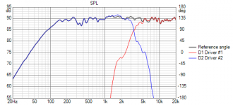
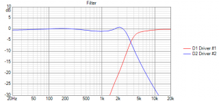
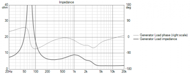
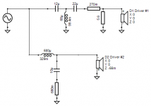
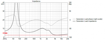
Hey guys, I've designed a new crossover. Can you take a look at the impedance curve and tell me if the new crossover design is a viable one. It seems the impedance after 5k remains pretty much the same no matter whatever design I try with this tweeter.
I'm using Faital Pro 5Fe120 8ohm for the woofer and Dayton TD20F 4ohm for the tweeter.
I have considered using other tweeters but the only available tweeters here in India that fit into my budget are the Dayton Audio ND13FA, ND20FA, ND16FA, and the Peerless TL25AN. I've tried simulating with all these tweeters but I am yet to find a frequency response curve that I like. (I want to achieve somewhat of a flat response in between the 2k-5k region without any major bumps)
Also, a couple of other doubts.
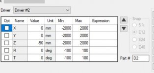
1. The alignment of the tweeter and the woofer is not the same right? The point of origin for sound for the woofer is behind the tweeters. So do we take that into consideration when we design a crossover usually? I did and I've initialized the value of -56 into the Z-axis value for the woofer and then gone on to design the crossover. Is this wrong? Or should I ignore this?
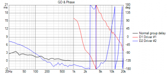
2. I've had to inverse the polarity of the drivers. Now inversing the polarity of the tweeter gives me a different phase curve and inversing the woofer gives me another. Now my question is how what do we look for at those Phase graphs.
Hey guys, I've designed a new crossover. Can you take a look at the impedance curve and tell me if the new crossover design is a viable one. It seems the impedance after 5k remains pretty much the same no matter whatever design I try with this tweeter.
I'm using Faital Pro 5Fe120 8ohm for the woofer and Dayton TD20F 4ohm for the tweeter.
I have considered using other tweeters but the only available tweeters here in India that fit into my budget are the Dayton Audio ND13FA, ND20FA, ND16FA, and the Peerless TL25AN. I've tried simulating with all these tweeters but I am yet to find a frequency response curve that I like. (I want to achieve somewhat of a flat response in between the 2k-5k region without any major bumps)
Also, a couple of other doubts.
1. The alignment of the tweeter and the woofer is not the same right? The point of origin for sound for the woofer is behind the tweeters. So do we take that into consideration when we design a crossover usually? I did and I've initialized the value of -56 into the Z-axis value for the woofer and then gone on to design the crossover. Is this wrong? Or should I ignore this?
2. I've had to inverse the polarity of the drivers. Now inversing the polarity of the tweeter gives me a different phase curve and inversing the woofer gives me another. Now my question is how what do we look for at those Phase graphs.
Attachments
Last edited:
Try changing from an L-pad on the tweeter to just series resistance either before or after the caps or both. That should help.
Yes you need to account for the drivers' acoustic center differences. Best way to get it right is with a mic and measurements - Box. The method is easily adapted for XSim so it should work for whatever program you are using too. Otherwise you have to take your best guestimate from the spec sheets' physical diagrams. If the program you are using is like PCD, your woofer should have a different y value than the tweeter too. The x value should be different too if the drivers are not vertically aligned.
It's common to have to reverse the polarity of 1 driver. Once reversed, you try to align the phase in the region of the xo as best you can. Third order electrical on the tweeter and 2nd order electrical on the woofer usually work well when the drivers are both flush on a vertical baffle.
I've removed the parallel resistor from the L pad and changed the value for the tweeter inductor. Now the impedance curve has a minimum value of 2.8 ohms. Will I be able to use a class D 4-ohm amplifier?
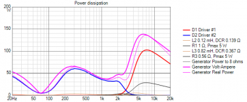
The woofer is rated at 80 watts and tweeter is rated 20 watts.
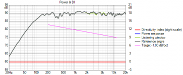
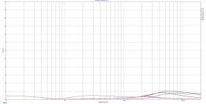
Also, I am using Vituix for the simulation. There's a Power Dissipation feature that provides a graph (I've attached an image). What do we have to look at that graph?
The woofer is rated at 80 watts and tweeter is rated 20 watts.
Also, I am using Vituix for the simulation. There's a Power Dissipation feature that provides a graph (I've attached an image). What do we have to look at that graph?
Attachments
Okay, lets have a look ... 
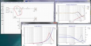
I've redrawn your crossover in XSim which is what I use.
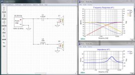
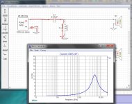
Take a look at the first thumbnail. By opening the currents panel we can see that L1 is shunting huge amounts of current to ground, starting at about 1 khz. This happens because C1 is a very high value and in series with the coil it forms a virtual short circuit to ground. This will cause a lot of heat in your amplifier and might even damage it.
There are some general rules here...
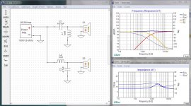
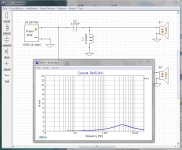
Now lets look at thumbnail #2... this is a classic 1st order crossover. There is a cap in series with the tweeter and a coil in series with the woofer. All current goes through the speaker voice coils so it is very efficient. As a learning exercise you should load this into your simulator and alter the values of the cap and coil ... increase the cap's value, what does the tweeter response do? Decrease it's value, what happens? Now do the same with the inductor noting the woofer's response.
In a many cases, with well chosen and well behaved drivers, this is all that is needed.
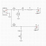
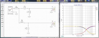
Now lets move on to thumbnail 3 ... This is the 2nd order circuit most people prefer. Note that the values from the 1st order design are not changed. In this case you are adding parts to fix a problem. There is a bit of wasted current here but it also gives a better change over from woofer to tweeter, avoiding some of the unpleasantness woofers can cause as they get above their ranges. You should load this into your simulator and play with the values of L1 and C2 to see their effects on the response curves. Increase and decrease the values as you did before... note their effects. Also note that you can cause real havoc if you get carried away.
I always start with 1st order and add parts only as needed.
Hopefully, by now you will see the mistakes in your original design and can set yourself off on a more successful redesign.
I've redrawn your crossover in XSim which is what I use.
Take a look at the first thumbnail. By opening the currents panel we can see that L1 is shunting huge amounts of current to ground, starting at about 1 khz. This happens because C1 is a very high value and in series with the coil it forms a virtual short circuit to ground. This will cause a lot of heat in your amplifier and might even damage it.
There are some general rules here...
- Any current that is not flowing through a voice coil is wasted energy and tends to make an amplifier work harder.
- Capacitors become more conductive as frequency increases.
- Inductors become less conductive as frequency increases.
- Resistors conduct more or less equally at all frequencies.
- The first element in each chain should do the most work.
Now lets look at thumbnail #2... this is a classic 1st order crossover. There is a cap in series with the tweeter and a coil in series with the woofer. All current goes through the speaker voice coils so it is very efficient. As a learning exercise you should load this into your simulator and alter the values of the cap and coil ... increase the cap's value, what does the tweeter response do? Decrease it's value, what happens? Now do the same with the inductor noting the woofer's response.
In a many cases, with well chosen and well behaved drivers, this is all that is needed.
Now lets move on to thumbnail 3 ... This is the 2nd order circuit most people prefer. Note that the values from the 1st order design are not changed. In this case you are adding parts to fix a problem. There is a bit of wasted current here but it also gives a better change over from woofer to tweeter, avoiding some of the unpleasantness woofers can cause as they get above their ranges. You should load this into your simulator and play with the values of L1 and C2 to see their effects on the response curves. Increase and decrease the values as you did before... note their effects. Also note that you can cause real havoc if you get carried away.
I always start with 1st order and add parts only as needed.
Hopefully, by now you will see the mistakes in your original design and can set yourself off on a more successful redesign.
Attachments
Last edited:
Okay. So what should the graph in the current panel look like? Flat?
Open the current panels in the two examples I gave you... Understand that any current that flows in a crossover or speaker has to come from the amplifier and thus places a load on it. The challenge is to design both for safety and efficiency. Bad crossovers do kill amplifiers.
Crossovers do not exist in a vaccuum, they are part of an overall system consisting of the speaker drivers, themselves, the amplifier and the speaker wires. You need to see the whole picture.
And some of the values in your simulation was not what I used. I did put the correct values in XSim and then captured the graphs.
Okay... sorry about that, a couple of your drawings were not clear.
At any given frequency...
High value capacitors conduct more than low value capacitors
Low value inductors conduct more than high value inductors.
For the moment lets concentrate on the nasty current path, shown in the first thumbnail, below... The capacitor you've used is a relatively high value which means it is conducting too much, too low in frequency. The coil you've used is way too low of a value which means it is conducting too much at too high of a frequency. This is causing a short circuit path through C1 and L1 (in the thumbnail)
In the current panel, note that it hits 13amps at about 5khz.
Now lets just change to a lower valued cap and a higher valued coil, as in the second thumbnail. See the difference in the wasted currents?
The difference is this... In my design the impedance (relativel conductivity) of the capacitor is used to block most of the low frequency energy. The coil is used to sharpen the roll off. But in your design your capacitor is conducting way too much below your crossover point and you are using the inductor to shunt off the excess current ... and that can kill an amplifier.
Go back to my real simple examples (both of which I use all the time). Open the current panels (Menu-> Add Graph -> Component Current) and look at the currents of the parts as you tinker with the values.
Jack up the power on the amplifier in your sim to that of your power amp.
Always build from first order as a starting point
Get the crossover points correct for your drivers.
Add parts only as needed.
Monitor currents at all times while working.
How much current should you expect?
HERE is an easy to use online calculator that will tell you.
For example... a 100 watt amplifier on 8 ohms expects to deliver about 28.2 volts resulting in 3.5 amps of current... obviously you want to keep your designs at or below that threshold. To draw more will cause more heat in the amplifier, it also robs the voice coils of current that produces sound, so your speakers rapidly become very inefficient.
Thumbnail 3 shows a simple setup I use to monitor currents. Note that I've added R1 at very low value to the circuit right on the amplifier's output. All current for the speaker passes through it, so it's a very convenient point to monitor. Obviously you would not include this part in your final design, it's only there as a monitoring point.
Attachments
Last edited:
attach the frd's and zma's zipped and XSim .dxo file so everyone has a chance at helping you, bearing in mind not to waste yours or anyone elses time.
This business of inefficient crossovers is something I'm seeing more and more, even in commercial products. Some of them are just ridiculous.
I suppose it's becoming something of a pet peeve....
Yes, our friend needs to give us the driver specs before we go much further.
He's already told us he's using...
Faital Pro 5Fe120 8ohm for the woofer and Dayton TD20F 4ohm for the tweeter.
Last edited:
Jack up the power on the amplifier in your sim to that of your power amp.
Always build from first order as a starting point
Get the crossover points correct for your drivers.
Add parts only as needed.
Monitor currents at all times while working.
How much current should you expect?
HERE is an easy to use online calculator that will tell you.
For example... a 100 watt amplifier on 8 ohms expects to deliver about 28.2 volts resulting in 3.5 amps of current... obviously you want to keep your designs at or below that threshold. To draw more will cause more heat in the amplifier, it also robs the voice coils of current that produces sound, so your speakers rapidly become very inefficient.
Thanks a lot. This made a lot of things clear. I think I am starting to understand what you are saying.
A lot of DIY crossover guides fail to emphasize this part and since I lack the technical know-how of electronics, I was a bit oblivious to it.
A lot of DIY crossover guides fail to emphasize this part and since I lack the technical know-how of electronics, I was a bit oblivious to it.
A lot of those DIY gurus are also plenty oblivious. I even got booted from a couple of their sites for pointing it out...
The problem is that nobody seems interested in the theoretical understanding of electronics anymore. They view Sims like XSim as a puzzle, building things like they were playing a video game. I've even seen it in a few commercial speakers as well... Everyone wants to play the game, nobody wants to learn the rules.
To successfully design anything, you need to know how each of the individual parts work. Short of that... well... outcome not guaranteed.
Stick with the guidelines I gave you... Start from first order, add stuff reluctantly, watch those part currents... you'll do alright.
Last edited:
This is one of two trends I'm seeing lately. The other is to obsess over the flatness of the impedance. Maybe there is a tutorial out there that some people are misinterpreting for some reason?This business of inefficient crossovers is something I'm seeing more and more,
If someone wanted to post a tutorial on how to do mosaic floor tile patterns, could they assume the reader knows, or will learn how to prepare the surface and use the adhesive, clean up etc?ikidnextdoor said:A lot of DIY crossover guides fail to emphasize this part and since I lack the technical know-how of electronics, I was a bit oblivious to it.
If someone wanted to post a tutorial on how to do mosaic floor tile patterns, could they assume the reader knows, or will learn how to prepare the surface and use the adhesive, clean up etc?
Haha, I think me trying to understand where I'm making mistakes is part of that learning process ��. Thankful to everyone that is helping guys like me out there.
Also, since the knowledge gained from the internet doesn't have the structure of what you get academically, there's bound to be a gap in between. Hence, such confusion.
Last edited:
I've traced them for the woofer (Faital Pro 5Fe120) and for the tweeter (Dayton Audio TD20F), I have used the files available on Parts Express. I doubt they include any baffle effects.
What I was thinking was to just chamfer the edges and not place the tweeter at the center. I'm having enough confusion with the crossover, did not want to complicate it more.
What I was thinking was to just chamfer the edges and not place the tweeter at the center. I'm having enough confusion with the crossover, did not want to complicate it more.
You're talking about the variations through the treble, I was thinking about the larger step in the midrange.
Okay this made realise I do not have clarity about the topic of discussion here. I think I'll read more about it and then engage in a discussion.
This is one of two trends I'm seeing lately. The other is to obsess over the flatness of the impedance. Maybe there is a tutorial out there that some people are misinterpreting for some reason?
Yeah, that too ... But then look how many people still fuss over the impedance of RCA cables and try to match up their eqipment. The whole "Synergy" thing with exactly matching output and input impedances went right out the window with solid state amplifiers and Impedance Bridging sometime back in the 70s ... but we still see it today.
Impedance wise the real worry is "Am I going to kill an amplifier?"... minor variations really don't matter that much. My current speakers (A pair of Dayton T652s) that I'm messing with start life as 4 ohms and end up at 8+ ohms by the time the tweeter is going. It's all within safe tolerances, but it is all over the place.
There has always been a ton of really bad info in the audiophile world. The only difference, now vs then, is that back then there were lots of people who darned well knew better. Now, not so much.
If someone wanted to post a tutorial on how to do mosaic floor tile patterns, could they assume the reader knows, or will learn how to prepare the surface and use the adhesive, clean up etc?
They should not. But you can bet someone did or will...
Last edited:
- Status
- This old topic is closed. If you want to reopen this topic, contact a moderator using the "Report Post" button.
- Home
- Loudspeakers
- Multi-Way
- Crossover Design: Low Impedance after 5k in the Impedance Curve