Hi,
I'm looking for hat is correcting 1R//10 uF in serie on the tweeter signal please ?
The tweeter is a 4 ohms nominal impedance (3.5 measured at voice coil) and XO is a LR4 at 2700 hz. this RC is between the two coils.
I looked for on line calculators but found at best RCL notch spreadsheet.
I assume this RC in serie with the signal gives a bump a the bottom or middle frequency of the tweeter to match the mid driver at corret spl but I can't find the frequencies windows involved by these RC values.
Are you please aware of a link about such frequency network correction please ? Bagbys's excells ?
Hum, I have tried Xsim free soft, starting from a LR4 with the amp tuned at 4 ohms... (not sure Z of driver can be setuped in Xsim ?) :
the climbing curve is starting slowly from 20 K Hz dB to end at 5.5 k Hz at +3 dB (flat between 4.9 k & 6.7 k) then falls from 4.9 k to 3.6 k Hz 0 dB.
assuming esr of lytics are flat at all frequencies ?!
Edit : seems to be the result of the filter cause the R//C is not working, same result with and without... so back to the beginning
Last edited:
Yes, it can.(not sure Z of driver can be setuped in Xsim ?)
Mostly in the audio band, yes.assuming esr of lytics are flat at all frequencies
Attachments
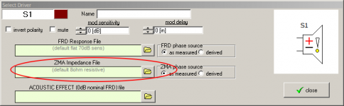
Vifa AC25SG05, but how do you generate this impedance file ?
Thank you AllenB, there is no real needs so please don't waste time. It's more about to understand about such R//C in serie behavior on the frequency curve. So I undestand the resistor is about the spl correction, but I just don't understand the C value which is I assume to be the starting corner of the climbing frequency... Maybe if I enter the C value in a first order on line calculator it may give the frequency where it starts ? the low end being the tweeter high pass filter before this serie R//C?
Or learn to generats such files for this smart Xsim soft... I'm about to dig out threads about it, how to or manual if exists.
In real life I sure will need of complex tool as a LCR bridge handtool to measure speaker parts but I haven't, or build something with Arta to measure a driver out of the box...
In the meantime I really understand what is this serie R//C on a tweter as lifting up the SPL when the frequency is progressing towards the cut off means more tweeter cone movements, so more distorsion and less precision due to more amplitude in the Xmax range.
Of course I'm a noob and just read the Dickason cooking book so my basic understanding is low and just on the theory side...uh !
You haven't shown your schematic. I guess that it is interesting what frequency the capacitor equals 1 ohm as well.
You can use a program to trace it for you, or you can type it by hand into a text editor while looking at the plot.how do you generate this impedance file ?
 Thank you AllenB !
I just have been understanding the need of accurate driver measurement on all the driver impedance curve from Pano member in a thread to play with such filters simulators. I naivly was thinking it was simplier and just had to enter the nominal impedance of the driver in a calculator...
He advised me the driver tester kit 2 from Smith&Larson, a fire and forget (pun intented) over the Dayton analyser V3. Cause it gives a zma file of the impedance on the whole frequency window of the driver !
I now understand why I didn't find an on line calculator for that.
I think my curiosity is definitly shooted by the price of such kit - while being not so much expensive at 150 usd- as I don't design speakers or often refurbishing old speakers. And having no issue with the filter but changing few lytics, it's more a no buy & forgett.
I will try to learn how to generate such text files from drivers curve & datasheet to understand the behavior of such filters...theorically. I eventually get such tools if I jump to play for real.
best regards
Last edited:
I measure impedance by connecting a speaker to my soundcard/computer. Nothing to buy. Just some wire and resistors. Free software is some of the best measurement software. Just saying..the price
Both of those will work. They don't do it for you, you have to do it manually.
For example, run your amp into a 1k resistor in series with a 10 ohm resistor. Plot the Voltage across the 10 ohm resistor vs frequency. Set the level so it measures something like 10mV. Replace it with the speaker. Trace the plot. Derive minimum phase.
For example, run your amp into a 1k resistor in series with a 10 ohm resistor. Plot the Voltage across the 10 ohm resistor vs frequency. Set the level so it measures something like 10mV. Replace it with the speaker. Trace the plot. Derive minimum phase.
understatment of R//C values
So playing a little with Xsim which default library speaker model is 8 ohms flat impedance rated, my understanding of the R//C in serie with the driver :
C value is giving the low end limit of the spl curve renforcment i.e the top of the climb towards the low frequencies cut off, i.e. spl is climbing as the frequency goes back.
For illustration: if C = 6.8 uF a first order high pass is giving circa 5850 Hz
below 5850 the spl dropes 8 dB per octave if acting as a first order high pass.
R is giving the spl amplitude of the highest spl renforcment which is at XO position, here for the illustration 5850 Hz.. then the spl is slowly droping towards the higher frequencies till the high end sp level given by the tweeter raw spec, for instance, 0 dB (flat) at 20 kHz, spl is the effecitienty of the raw driver here, for instance 90 dB/2.88 V.
For 1R I have a 3 dB bump and the more I raise R value the less the low-end spl increases which will give a total smoother curve; for illustation with 1R5 the bump is 1.5 dB only.
Am I right or not please about the mechanism of this serie R//C frequency correction filter, please ?
R being a simple wirewound cement resistor : has it an increase of inductance following the frequency increase of the curve ? Said differently, does it give an hearable low pass as an inductor effect in the high end, shorting sooner the curve than without the resistor ? Better an Ayrton Perry type here or a bulk resistor or simply can not be heard ?
I advance appologize for these 2 cents questions.
Also as an icing of the cacke ,what is the effect on the phase of such filter please ? Better to avoid such filter ?
Again, you haven't shown me your schematic, I have to guess.
Here is my guess.. Look at the frequency where the capacitor equals 1 ohm. Below this the parallel combination acts like a resistor and above this it acts like a short circuit. This causes the higher frequencies to tilt up, (actually the lower ones to shelve down).
Here is my guess.. Look at the frequency where the capacitor equals 1 ohm. Below this the parallel combination acts like a resistor and above this it acts like a short circuit. This causes the higher frequencies to tilt up, (actually the lower ones to shelve down).
Very small. Not a problem at audio frequencies.wirewound cement resistor : has it an increase of inductance
If it gives you better response, then use it.what is the effect on the phase
Thank you so much AllenB,
I realise I missunderstood the Dickason book about it. the shematic is not so clear and I understood. I thought it was the lowest frequency till the shortcut that tilted up... and it's quite the oppositt... Great step up for my understanding
I thought it was a bobsleigh curve and it's a launching ramp instead
I didn't give you the values for two reasons : my original question was about to understand the concept for any crossover and refering to the crossover I study I haven't the inductances values nore the exact capacitances. I just see it is in the midle of a LR4 cause there are 2 shunted inductances.
Ok for the phase, curve is more important first, so forgett the phase if you need to correct the curve.
So the idea to choose the capacitance as a starting frequency (first order serie cap) is good but the curve will tilt up towards the highest frequency. the higher the Z of the resistor the stiffer the launching ramp and I assume the spl bump at the end is the independance curve at the frequency level + the Z of the resistor ?
Am I right know ?
Sorry to have not a LCR to give you filter values for a proper more precise illustration, but I haven't a LCR yet...and frankly it doesn't matter for my understanding. I still have to build a diy box for that to use with a Arta or Rew to measure in real life and see the result in a real filter... one step at once
Thank you again AllenB, your help is much appreciated. I wanted first to understand the mechanism of this serie R//C. So the behavior is near a L-pad ... sort of.
AllenB, I have a doubt at reading my old edition of the Dickason coocking book,
Does it tilt down the spl just after the short instead, so at the beginning jut after the frequency given by the cap without tilting up the high end ? That's the picture on the book that introduce a doubt ?!
Does it tilt down the spl just after the short instead, so at the beginning jut after the frequency given by the cap without tilting up the high end ? That's the picture on the book that introduce a doubt ?!
Your understanding is much better.
There are inductors, and the driver impedance is not simple. Anything is possible.Does it tilt down the spl just after the short instead, so at the beginning jut after the frequency given by the cap without tilting up the high end ? That's the picture on the book that introduce a doubt ?!
Hum...indeed... that's why I ask! in his book Dickason said one is in the dark with these corection circuits.... and must go with trial and error...so one have to understand the inductors in shunt play a role...in the RL4 indeed there is a shunted coil after the serie R//C... so a part of the current is gojng througj the coil and the tweeter in the same time....hoping the formulas in the soft are working well for such circuits...
Thank you gentlemen
Thank you gentlemen
- Status
- This old topic is closed. If you want to reopen this topic, contact a moderator using the "Report Post" button.
- Home
- Loudspeakers
- Multi-Way
- frequency amplitude R//C serie correction