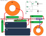
Good morning, I have to build xover starting from a scheme generated with Boxsim. I would like to use wood tablet and solder tag strips. How can I "translate" draw into real xover? In annex an example taken on net. Are there tips, tricks, techniques to make right construction, respecting all connection? Many thanks in advance.
Ziocalepino
Ziocalepino
Attachments

Somewhat contrary to what's stated in the inductor testing layout about what's good and what isn't, if the inductors are air core types, as long as there are 2 inches of spacing between the coil perimeters of adjacent inductors, both coils can be laid down flat, not needing to stand one up. If, however, room is limited, you may need to stand one up as suggested.
Paul
Paul
Good morning, I have to build xover starting from a scheme generated with Boxsim. I would like to use wood tablet and solder tag strips. How can I "translate" draw into real xover? In annex an example taken on net. Are there tips, tricks, techniques to make right construction, respecting all connection? Many thanks in advance.
Ziocalepino
The physical layout does not need to look like the schematic drawing. When placing your parts try to have as few wires crossing one another as possible to avoid shorts. Also keep inductors as far apart as possible to avoid interactions.
But there is something else you need to consider...
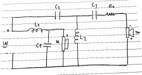
1) Looking at your schematic you have R4 bypassing the coil in your low pass filter. This will limit it's ability to shut down the woofer as frequency increases which could affect sound by making woofer breakup audible.
2) You are also bypassing the woofer coil with the combination of R5 and C2. Capacitors are most conductive at high frequencies. This will also tend to prevent the woofer from being shut down and might actually result in treble being reproduced from the woofer.
In general when designing crossovers it is best to have the high pass capacitor as your first part on the tweeter branch and the low pass inductor as the first part on the woofer branch. This is to ensure proper isolation between the high and low pass elements. Bypassing those lead parts is generally a bad idea because it limits the isolation between branches and can limit the roll off slope of that branch.
Last edited:
2) You are also bypassing the woofer coil with the combination of R5 and C2. Capacitors are most conductive at high frequencies. This will also tend to prevent the woofer from being shut down and might actually result in treble being reproduced from the woofer.
You'd have to complain to Troels Gravesen for that one I think
") It was just an example, not his actual filter.
It was just an example, not his actual filter.In fact my actual filter is the one posted above, simpler than Troels' one. But a problem for me!
No... your pencil drawing looks fine.
But I keep running into this cap across the woofer coil thing and when I see it I generally try to point out how dangerous it can be for an amplifier.... I don't know where this started but it seems to be everywhere, these days, and now it's getting into help files and text books but nobody seems to realise that it's a problem.
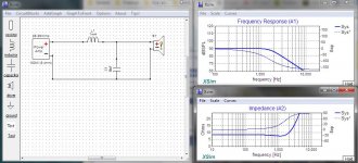
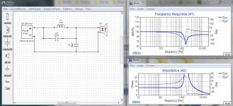
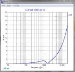
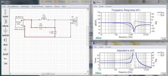
The first thumbnail below is a bog standard 2nd order low pass. It will work as expected.
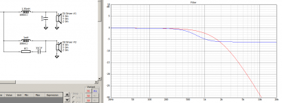
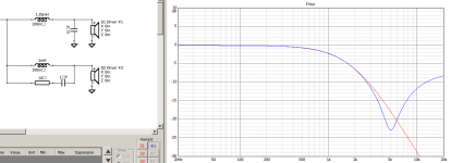
The second thumbnail shows the addition of C2 right across the woofer coil. Look at the frequency response, it is true the woofer falls off like a rock, but then it begins rising and becoming more active, which is undesirable.
But the real story is in the third thumbnail where we see that C2 is causing C1 to handle upwards of 15 amps at 20khz... That's an amp-killer.
Once again ... your drawing looks fine. Sorry for the confusion.
Attachments
Hi Allen ... in the configurations you have the cap across the coil really isn't a problem. It's when you add that to a second or third order crossover that you get the problem.
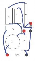
From my second thumbnail in my previous post I've marked the current path that causes the problem.
What happens is that at higher frequencies C2 begins bypassing the coil and C1 is a very low impedance so you get a virtual short circuit from the two caps acting in series.
From my second thumbnail in my previous post I've marked the current path that causes the problem.
What happens is that at higher frequencies C2 begins bypassing the coil and C1 is a very low impedance so you get a virtual short circuit from the two caps acting in series.
Attachments
- Status
- This old topic is closed. If you want to reopen this topic, contact a moderator using the "Report Post" button.
- Home
- Loudspeakers
- Multi-Way
- Converting drawing to physical xover