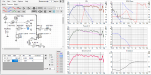
Hey there, I'm just playing with Vituix for the first time. Really have never worked on crossovers before or soldered. I was wondering if someone could critique this design I've come up with. Its a 2 way using a horn mated to a B&C DE750TN 2" compression driver. The woofer is a 15" B&C. I'm trying to get the best response possible. I don't mind the bass being slightly light being that I'm in a condo.
There's a couple things I am completely confused about however. I don't understand how to determine the impedance of the two capacitors I've put in here. Does anybody know?
There's a couple things I am completely confused about however. I don't understand how to determine the impedance of the two capacitors I've put in here. Does anybody know?
Attachments
For the purposes of crossover the ESR doesn't matter too much, you can set it at 0.1 ohms and leave it there. That's a little higher than nominal but as you'll see it makes very little difference because the series resistor swamps the value of the capacitor ESR.
Is there a specific reason you used that topology? It looks quite unusual.
Is there a specific reason you used that topology? It looks quite unusual.
Is there a specific reason you used that topology? It looks quite unusual.
Basically, it chose me

I fiddled around until I got the frequency response I wanted. My goals with this design are to
use the 2" as low as possible and make the system as phase coherent as possible.
I wanted to have the 15" and the 2" low to minimize beaming. At the same time I chose a 100db sensitive woofer because I'm hoping it will keep up better with the 2". I had to do a notch around 100hz to knock down a nasty woofer bump and I got more around 50hz which is nice. I'm just wondering whether this design will be safe on the drivers. I plan to run the 2" with no high pass and just let it roll in naturally. Is this a bad idea?
The impedance is a quite a big issue, as you're trying to use shunt filters for the tweeter and this places the amplifier in peril. I think you could achieve something similar with a more conventional topology. I'm not familiar with the drivers you used, a 2" CD should be just about able to hit the 400Hz XO point you chose, but I'm not sure it will like it.
I'm concerned about the 200uF to ground after the 8mH coil. Looking at the woofers natural impedance curve it's minimum is around 7 ohms, and it is significantly higher 100Hz and below. I think you will be stressing your amp unnecessarily. It looks like your impedance curve is dipping to around 4 ohms 100Hz and below.
Tony.
Tony.
The impedance is a quite a big issue, as you're trying to use shunt filters for the tweeter and this places the amplifier in peril. I think you could achieve something similar with a more conventional topology. I'm not familiar with the drivers you used, a 2" CD should be just about able to hit the 400Hz XO point you chose, but I'm not sure it will like it.
Ok great thanks for the info! I will try and tweak the crossover there up 100hz and report back.
I'm concerned about the 200uF to ground after the 8mH coil. Looking at the woofers natural impedance curve it's minimum is around 7 ohms, and it is significantly higher 100Hz and below. I think you will be stressing your amp unnecessarily. It looks like your impedance curve is dipping to around 4 ohms 100Hz and below.
Tony.
I'm not crazy about using those expensive capacitors either! I will try and raise the impedance for the woofer below 100hz and raise the capacitors there and report back. Thanks for the input. would something closer to 100uF caps be safer or should I try and get rid of the caps altogether?
Last edited:
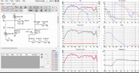
How's this?Put in 100uF and see what it does to the impedance curve in the lower left box. I'm not good enough at mentally working out what frequencies will be affected by particular components, but I'm reasonably sure that cap is at least contributing to the impedance dip.
Tony.
I did the best I could with frequency response, keeping the notch around that massive 100hz bump. I raised the impedance of the woofer below 100hz and limited max cap size to 100uF on the circuit. I also did a high pass and knocked just over 100ish hz off the bottom of the DC to give it less stress. I was hoping to run it closer to its 500hz cutoff, but I dont want to strain it. And to boot this will be a cheaper crossover
Anything else looking concerning here? I dont want to fry anything lol
Attachments

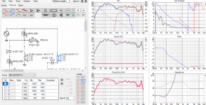
The 60u and 22 ohm should not be there. They should be having no effect other than to tax your amplifier (if it is a typical amplifier).
Your tweeter impedance will have a significant effect. Did you measure it on the horn you intend to use?
I put them there because they seem to to align and match the impedances. Maybe this is pointless? Isnt it ideal if the speakers have a similar impedance curve? take a look with and without:
Attachments
No. This shouldn't make any difference to an ideal amp. (Of course amps are not always ideal, but for now, this is not very important.)Isnt it ideal if the speakers have a similar impedance curve?
It appears that you are just wanting to learn about using VituixCad to design filters (but not doing a full crossover). If you want, we can just ignore the horn and pretend the response you have is correct. This way you can get on with learning, does that fit with your plans?
EliGuy, it looks like you are trying random stuff and seeing what it does. That is ok from a learning pov (up to a point) but it might be good to have a grounding in the basics of how things work first.
If you haven't already have a read through AllenB's excellent thread Introduction to designing crossovers without measurement
Also have a read of this http://www.pispeakers.com/Speaker_Crossover_Lab.pdf It should give you a good grounding. is also an excellent primer.
The impedance looks much better now you don't have that 200uF cap direct to ground, but you are being extremely unconventional. With the impedance, having the different drivers match is not really that important (maybe not true for some valve amps), the final impedance presented to the amp (across the frequency range) ensuring no perilously low dips, is going to be the most important aspect.
I've not looked at your 2" driver, but having that much resistance in series with it I struggle to see how it can be contributing much to the overall sound at all (though the graphs would indicate otherwise) is it a piezo?...
Tony.
Last edited:
No. This shouldn't make any difference to an ideal amp. (Of course amps are not always ideal, but for now, this is not very important.)
It appears that you are just wanting to learn about using VituixCad to design filters (but not doing a full crossover). If you want, we can just ignore the horn and pretend the response you have is correct. This way you can get on with learning, does that fit with your plans?
Thanks. I definitely don't know what I'm doing and surely the model I have built wont reflect the real response that I'll get. I've actually got the DE750TN's on the way (picking up tomorrow) And I'm building a set of horns with the OSWG excel file I found on here. Lol, should be interesting. We'll see how they actually measure once I've got something put together,. Then once I've measured them and received some type of woofer I was planning on trying to build a real crossover. I realize this is extremely ambitious, but I have too much time on my hands lately and I enjoy the challenge.
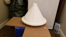
Here's the mould being constructed...based on oblate spheroid dimensions...getting the throat angle is definitely not easy but I found its 22 degrees and put that into my waveguide calcs..
Attachments
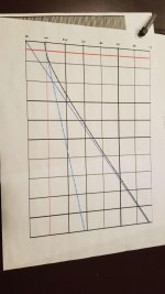
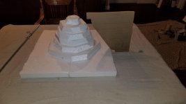
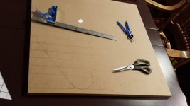
Judging by the dimensions on the paper I'd guess this is 33 degrees half angle (66 degrees total). This is a little ambitious as it is a narrow angle, this just means it will have to be longer and larger to do its job properly.
At what axial point do you plan to start bringing it out?
At what axial point do you plan to start bringing it out?
Judging by the dimensions on the paper I'd guess this is 33 degrees half angle (66 degrees total). This is a little ambitious as it is a narrow angle, this just means it will have to be longer and larger to do its job properly.
At what axial point do you plan to start bringing it out?
Yeah, really just an experiment..Most horns I've seen online tend to be in the 90x40 or 60x40 wheelhouse. I've got a small condo and sit about 12 feet from them so I figured 66 degrees was about right to minimize room interactions. Could be wrong...But I can always build another one.
My adapter will add on 1/2". I'm going to remove a bit from the horn and do my darndest
to match the throat angle of the CD. I'm sure it wont be perfect, but it'll be an adventure.
So the notch is a bad idea hey. Perhaps I should look at another driver for bass. I dont need a tonne of bass as I cant really crank my system here anyways. Im more interested
in great mid range and lower level critical listening. Any suggestons on a bass driver?
- Status
- This old topic is closed. If you want to reopen this topic, contact a moderator using the "Report Post" button.
- Home
- Loudspeakers
- Multi-Way
- 2 Way Crossover