For one, the resistance of the inductors needs to be investigated as these have a significant enough effect on the bass end and could take away some of the benefit.
A second issue is your wanted lower cross. This could change the performance of these and the components needed and the overall sensitivity. Thirdly, better to get the raw woofer impedance and redo things.
For now, It would be good to confirm whether you are talking more about the upper bass level giving a flat enough response for voice reproduction, or if it is the lower frequencies. It would be good to just confirm whether the region this fixes helps or not. If you have some components lying around that are similar, maybe they can be used in a custom crossover revision. Let us know if you have interesting parts.
OK, let me address these questions one at a time.
The stock low-pass 1.75 mh inductor (large gauge) reads 0.5 ohm resistance
The stock high-pass 0.22 mh inductor (small gauge) reads 0.3 ohm resistance
Second issue I'm not quite following, what do you mean by wanting a lower cross?
I measured the voice coil resistance of both raw woofers at 5.1 & 5.2 ohm
I don't have a woofer tester to do anything passed basic multimeter
Lastly, to my ears the bass problem is mostly lower bass and mid bass, not upper mid bass. The mid-bass is real fast and dry, lean. Perhaps not enough mid bass, and definitely not enough low bass.
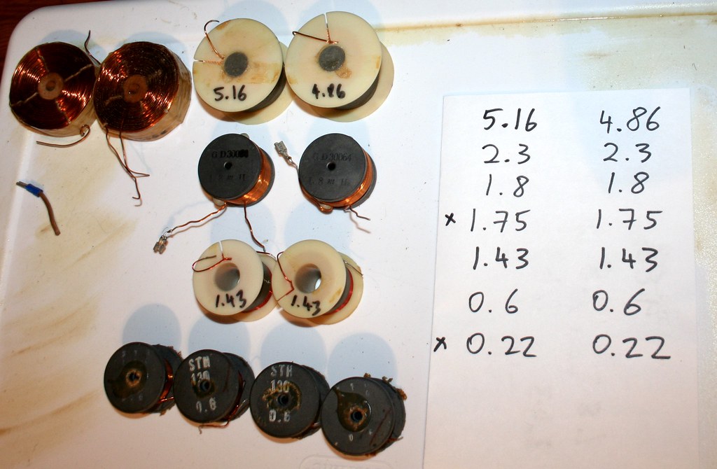
For components lying around, I've got almost every size resistor, almost every size cap from 0.01 to 47 uf, but with a 47 and 33 I can make that 80 uf you mentioned.
Now inductors are where I'm a little short. I laid them all out in a pic with specs. Not shown are the 1.75 & 0.22 of the stock XOs, and the 2.3 mh I'm using as my make shift BSC in front of the woofer filter right now. The top left pair of inductors is unknown value.
Hope that helps.
Last edited:
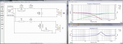
Thank you for the drawing. It shows a very basic Second Order crossover.
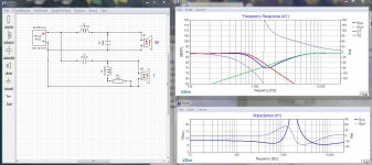
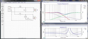
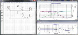
Modelling it in XSim, without knowing the exact driver specs...
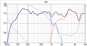
I got what you see in the first Thumbnail. The cross over frequency is about 1.4khz and that's quite the drop out at the upper voice range.
The second thumbnail differs only in that I've inverted the tweeter (reversed the connections) and it looks a lot better.
The third shows a little bit of parts tampering which seems to get it even closer.
Now I can't promise success with this, but I would at least try reversing the wires on those tweeters.
Modelling it in XSim, without knowing the exact driver specs...
I got what you see in the first Thumbnail. The cross over frequency is about 1.4khz and that's quite the drop out at the upper voice range.
The second thumbnail differs only in that I've inverted the tweeter (reversed the connections) and it looks a lot better.
The third shows a little bit of parts tampering which seems to get it even closer.
Now I can't promise success with this, but I would at least try reversing the wires on those tweeters.
Attachments
Last edited:
Just for clarification, I drew up what I'm running right now. I drew orange boxes around the parts I added, the rest is stock XO:
(I did reverse the tweeter polarity)
According to that online BSC calculator, that 2.3 mh & 5.2 ohm resistor should do 6db, but it doesn't sound like it, maybe more like 3db. Or it is actually doing 6db and the speaker needs 8db ?

(I did reverse the tweeter polarity)
According to that online BSC calculator, that 2.3 mh & 5.2 ohm resistor should do 6db, but it doesn't sound like it, maybe more like 3db. Or it is actually doing 6db and the speaker needs 8db ?
Last edited:
Just for clarification, I drew up what I'm running right now.
The thing to understand with baffle step compensation is that you are essentially attenuating the woofer above a given frequency. As the frequency rises, the added coil carries less and less current until it's all going through the resistor... so you are essentially knocking down the overall bass in favour of a bit more apparent low bass. This is not always a bad thing. But please be aware that 5.6 ohm resistor with a woofer measuring about 6 ohms will be carrying half the amplifier's power throughout the mid-bass region. So be sure it's of a rating to handle it.
Modelling what you have now shows only a modest increase in low bass with a general loss of output across the rest of the range. I'm not sure it's worth it.
My understanding is that these are ceiling speakers? Big ceiling speakers... In that case you should not need baffle step compensation since the ceiling (or wall) is part of the baffle. What you need to do is make sure it's not jammed into a corner... Keep it a couple of feet away from corners if you can.
If you have the joy of having it in a suspended ceiling, you can try different spots, within range, take REW scans from your sweet spot and pick the best placement for it.
Also please be aware that smaller speakers (5 or 6 inch) tend to fair better as ceiling or in wall speakers due to the often shallow area behind their magnets.
Attachments
Last edited:
The thing to understand with baffle step compensation is that you are essentially attenuating the woofer above a given frequency. As the frequency rises, the added coil carries less and less current until it's all going through the resistor... so you are essentially knocking down the overall bass in favour of a bit more apparent low bass. This is not always a bad thing. But please be aware that 5.6 ohm resistor with a woofer measuring about 6 ohms will be carrying half the amplifier's power throughout the mid-bass region. So be sure it's of a rating to handle it.
Modelling what you have now shows only a modest increase in low bass with a general loss of output across the rest of the range. I'm not sure it's worth it.
My understanding is that these are ceiling speakers? Big ceiling speakers... In that case you should not need baffle step compensation since the ceiling (or wall) is part of the baffle. What you need to do is make sure it's not jammed into a corner... Keep it a couple of feet away from corners if you can.
If you have the joy of having it in a suspended ceiling, you can try different spots, within range, take REW scans from your sweet spot and pick the best placement for it.
Also please be aware that smaller speakers (5 or 6 inch) tend to fair better as ceiling or in wall speakers due to the often shallow area behind their magnets.
Gotcha, good to know about the resistor power handling.
Yes they are ceiling speakers, but I'm misappropriating them into ported cabs as vintage style monitors. Either that, or mounting them in large towers with 15" helper woofers with plate amps for the 15s.
My understanding is that in a ceiling there's no need for BSC because the ceiling is an infinite baffle. I am however currently running them in cabs of 14.25" wide baffle and so I'm losing low frequency output. I think that even mounted in ceiling, they would've been bass shy. So I'm leaning towards 8db rather than 6db of BSC.
I know on paper the stock crossover has a huge hole in it, but that tweeter is very middy, it's almost like a mid-tweeter. Check out the manufacturer's published FR graph on page 1 of this thread. That is of course mounted on an IEC baffle / infinite baffle. So compared to that graph, I'm short about 6db of bass below 300 hz, but my ported cabs tuned to 53 hz also extend the low bass a little compared to that graph. This is what I've gathered so far, my ears kinda confirm it, but I could be wrong of course and I'm without measuring equipment.
Last edited:
This is what I've gathered so far, my ears kinda confirm it, but I could be wrong of course and I'm without measuring equipment.
The best thing I can suggest at this point is to get REW up and running on your computer/laptop, set the speakers up in their cabinets, and run a set of scans from your sweet spot and see what you get... You might be surprised!
(FWIW... I never bothered with the extra expensive USB mic for this, I just use a cheap lavalier mic, on my chest as I measure.)
In my own living room I was getting truly crappy bass response. I mean it was just bloody awful for quite a while. In what amounts to a fit of desperation I tried simply moving my speakers around within the area my furniture permits... 6 inches further apart and 2 inches closer to the wall and now I've got more bass than I can use. It turns out I was actually sitting in a cancellation node with the sound reflecting off the wall behind me. I now run my system without a sub-woofer.
This is to suggest that careful positioning can often do more than all the clever crossover tricks in the world. I wouldn't be too bent on rewiring or altering your initial plan until I got some actual in-room measurements from them. The joy of doing it this way is that you get speakers the are literally tuned to your room...

Also note that Tannoy has never been known for BIG bass.
Last edited:
You wanted to cross to a 15" driver. It is possible to do that without any compensation on the Tannoy woofer, letting the 15" fill in the bass. Alot depends on where you want to cross. If you want to cross at a lower frequency, then more needs to be done to compensate the Tannoy.what do you mean by wanting a lower cross?
Or maybe you want to increase the Tannoy bass as much as possible so you can enjoy them now, until you get the 15" and then remove it if necessary to cross them? (In which case there isn't a 6dB limit.)
The issue is that the cross overlaps the compensation, it might even cancel it.
The best thing I can suggest at this point is to get REW up and running on your computer/laptop, set the speakers up in their cabinets, and run a set of scans from your sweet spot and see what you get... You might be surprised!
(FWIW... I never bothered with the extra expensive USB mic for this, I just use a cheap lavalier mic, on my chest as I measure.)
In my own living room I was getting truly crappy bass response. I mean it was just bloody awful for quite a while. In what amounts to a fit of desperation I tried simply moving my speakers around within the area my furniture permits... 6 inches further apart and 2 inches closer to the wall and now I've got more bass than I can use. It turns out I was actually sitting in a cancellation node with the sound reflecting off the wall behind me. I now run my system without a sub-woofer.
This is to suggest that careful positioning can often do more than all the clever crossover tricks in the world. I wouldn't be too bent on rewiring or altering your initial plan until I got some actual in-room measurements from them. The joy of doing it this way is that you get speakers the are literally tuned to your room...
Also note that Tannoy has never been known for BIG bass.
For sure, I'm big on finding the best placement in any room. I've moved these all over the place in this room and finally settled in at the old sweet spot (well away from walls). The imaging and sound stage on these speakers is incredible. Treble, mids, mid bass are great and only a little more bass slam is missing and they'll be very, very sweet speakers. I will later experiment with my super tweeters as well as bypass caps, just wanted to get the basics right.
You wanted to cross to a 15" driver. It is possible to do that without any compensation on the Tannoy woofer, letting the 15" fill in the bass. Alot depends on where you want to cross. If you want to cross at a lower frequency, then more needs to be done to compensate the Tannoy.
Or maybe you want to increase the Tannoy bass as much as possible so you can enjoy them now, until you get the 15" and then remove it if necessary to cross them? (In which case there isn't a 6dB limit.)
The issue is that the cross overlaps the compensation, it might even cancel it.
Right, that was the initial plan. And I'd still LOVE to do that, but the reality of the cost will delay that a little. For now, I'd love to get them sounding right in a monitor size ported cab and enjoy them in my small listening room. I really enjoy the way they sound and image, on well recorded material. They are revealing and natural sounding.
Crossing at 300 hz to the 15" woofers would be perfectly fine with me, good to know that it can be that simple down the road.
Yes, for now I'd love to increase the bass a little more. It seems like 6db is just not quite enough. (I measured the 2.3 mh inductor I've been using as make shift BSC at 0.9 ohm resistance, it's a really small gauge)
Also a quick question about the high pass: Don't I place the series resistor before the cap, then one in parallel after the filter? Earlier you wrote one resistor after the cap and one in parallel after the filter, wouldn't the series resistor after the cap affect the high pass filter?
Can I use an adjustable l-pad with the tweeter and the factory high pass?
Thank you!
My understanding is that these are ceiling speakers? Big ceiling speakers... In that case you should not need baffle step compensation since the ceiling (or wall) is part of the baffle. What you need to do is make sure it's not jammed into a corner... Keep it a couple of feet away from corners if you can.
Douglas,
Chiming in as I have a set of these as well. They are intended for ceiling mounting, but in 2.6 ft^3 ported enclosures above suspended ceilings - see the attached data sheet for pictures. In a different sales brochure Tannoy says:
"Applications
• High ceiling applications
• Shopping malls
• Transport hubs
• Ballrooms
• Boardrooms / Corporate AV
• Convention Centres
• Cruise Ships
• Large Bars & Restaurants"
So, much more "pro-audio" than hi-fi. They are never going to make "big bass", and as KnR and I are (mis)using them will lose a bunch of what they do make due to the baffle step. Tannoy sells matching in-ceiling subs for the intended uses.
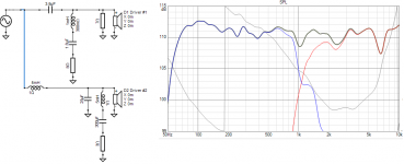
Also attached is my XSim model of the factory xover, which includes the measured 108 mm / 4.21" delay between the woofer and tweeter - a sim without the delay won't be too close to reality! I'd like to remeasure the FR's of the drivers in a better environment than my den but this does show how well the factory crossover works. It would probably help to be able to get further away. I should also use responses averaged over a window than the single-point sweep used in the sim.
I'm sidestepping the bass issue by crossing mine above the baffle rolloff using miniDSP. The woofers I'm using now are too inefficient to keep up, I need ~13dB attenuation on the Tannoys. The glue is drying on a test woofer box as I write that should be a better efficiency match (2 x 15" per side, sealed box with eq). At some point I'll bypass the passive crossover entirely and tri-amp the system. It remains to be seen which approach will stick. Or whether this is a fool's errand entirely.
Bill
Attachments
Thanks for the information. How does your enclosure compare to the one used in the measurement you posted? Ie impedance and response. I gather they are both ported. I was guessing that the factory rear chamber was sealed but I guess not. I can't find much on driver Vas etc. Just want to have an idea of what needs to be equalised.ported cabs tuned to 53 hz
This was a judgement call and it's worth explaining, and if you have variable L-pads then go ahead and try them in different positions. Putting the L-pad before the filter is going to increase its source impedance (to the value of the L-pad resistors in parallel). To what extent this is a problem, I'll let you find out with the L-pads.Don't I place the series resistor before the cap, then one in parallel after the filter? Earlier you wrote one resistor after the cap and one in parallel after the filter, wouldn't the series resistor after the cap affect the high pass filter?
After the filter could make a difference if the tweeter had impedance variations that were affecting the filter, because the L-pad reduces these variations. It doesn't change the impedance magnitude across the board, as one resistor is positioned to offset the other. I noticed the filter had a shunt element that would already be reducing impedance variations to some degree, so I though it would be more predictable to go with the flow.
Last edited:
This was a judgement call and it's worth explaining, and if you have variable L-pads then go ahead and try them in different positions. Putting the L-pad before the filter is going to increase its source impedance (to the value of the L-pad resistors in parallel).
After the filter could make a difference if the tweeter had impedance variations that were affecting the filter, because the L-pad reduces these variations. It doesn't change the impedance magnitude across the board, as one resistor is positioned to offset the other. I noticed the filter had a shunt element that would already be reducing impedance variations to some degree, so I though it would be more predictable to go with the flow.
Thanks for explaining! Will play around with the tweeter level, I think it could benefit from some impedance correction via parallel resistor. There's a bit of upper midrange peak on certain songs.
These are the woofer specs I could find, based on the assumption that this woofer is the same as the (I think) v12 / i12 PA cabs, forget the model # (3142 perhaps???).
Fs: 69
Re: 5.1
Zmax0: 31.29
Qms: 4.043
Qes: 0.786
Qts: 0.658
Vas: 37
Le (mh): 1.3
db: 93.85
Mms(gr): 61
Cms: 0.09
BL: 13.11
Last edited:
Thanks for the information. How does your enclosure compare to the one used in the measurement you posted? Ie impedance and response. I gather they are both ported. I was guessing that the factory rear chamber was sealed but I guess not. I can't find much on driver Vas etc. Just want to have an idea of what needs to be equalised.
Shoot, I don't have actual measurements of my enclosures. They're 48 liters, ported to 53 hz via 3 x 2" ports.
The posted measurements from the brochure are with the drivers mounted on a IEC test baffle, which I understand is an infinite baffle, so no porting. I think that's why the bass rolls off well above 100 hz, but there's no baffle step loss.
I could be wrong.
Chiming in as I have a set of these as well.
I'm sidestepping the bass issue by crossing mine above the baffle rolloff using miniDSP. The woofers I'm using now are too inefficient to keep up, I need ~13dB attenuation on the Tannoys. The glue is drying on a test woofer box as I write that should be a better efficiency match (2 x 15" per side, sealed box with eq). At some point I'll bypass the passive crossover entirely and tri-amp the system. It remains to be seen which approach will stick. Or whether this is a fool's errand entirely.
Bill
Thanks for chiming in. I look forward to hearing about your new subs playing with these Tannoys.
That sim you posted won't open on my macbook, any chance you could screen shot it and post it? Thanks!!
Been working on the high pass only for a while now.
One thing I have noticed, no matter how small a series resistor I use to pad the tweeter, it really robs the top end sparkle and makes the sound 'dark' (that's with and without parallel resistor).
(A note about my resistors, they're all Dayton wire wound 'audio grade', half of them already 'broken in' / not used for the first time. I do notice break in on these during the first few minutes when new, so I always wait a few minutes between making changes unless it's way off)
I've been trying different combos of series (2 - 4 ohm) and parallel (7 and 8 ohm) resistors.
I really wanted to make it work without series padding, as it robs the precious top end sparkle. I kept incrementally stepping down in series resistor values from 4 ohm all the way down to no series padding. With none, the tweeter is a little too loud of course, due to my BSC.
I then tried only a parallel resistor, first 8 ohm: still too loud but close
Then stepped down to 7 ohm and it puts the tweeter level in check, but also majorly transforms the tweeter response.
I originally was hoping the parallel tweeter would null the upper midrange peak that's noticeable on some program. However, adding a parallel resistor to the tweeter significantly smoothes out the mids WITHOUT robbing any of the top end sparkle.
I know, measurements would help.
Best way I can describe via my ears:
Before:
Studio monitor-like mids with tendency towards subtle midrange bloom (almost like a Klipsch but without the ice pick ramming into my ear drums, ie smooth, not shouty).
After:
Hifi like, slightly scooped mids now, great top end treble (top end unaffected, but less mids).
Needless to say I'm really excited about this. I will need to find the ideal value for the parallel resistor via more listening.
I realized that perhaps the parallel resistor makes the high pass sound in real life more like what the crossover would suggest on paper: a hole between the drivers, ie scooped mids. So I may start messing with increasing the 6.8 uf tweeter cap. But first I will listen for a while as is, it's quite pleasant but also less revealing. Maybe the perfect sweet spot is somewhere in the middle.
Last edited:

On one hand the hole is making up for a broad peak in the lower treble so there shouldn't really be a hole. Still, I think I like where you're going with this for now.I realized that perhaps the parallel resistor makes the high pass sound in real life more like what the crossover would suggest on paper: a hole between the drivers, ie scooped mids.
However the effect is going to be biased toward the low end where the series capacitor is filtering most, and also where the impedance was higher before adding the parallel resistor due to the amount of change (impedance plot).. and neither of these coincidences is necessarily tied in toward voicing.
Another option is to add a small capacitor in parallel with any series resistance to give back the highs.
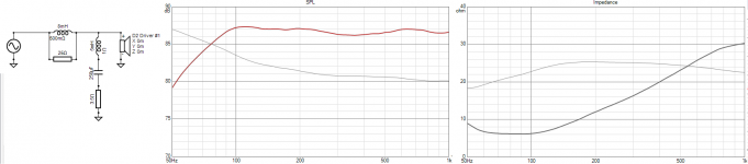
Hmm, with the double impedance peak I figured they were using the default enclosure. I tried to cut the low end down to something more common, and I used the plotted response. I also used the plotted impedance, with derived minimum phase. It's usually better with measurements, but there's a way.which I understand is an infinite baffle
The upper impedance peak became a limiting factor so I used a series notch filter in parallel with the driver. Before this, the response was cutting off well above 100Hz (or peaking if I pushed it), Getting -3dB at 70Hz required cutting the midrange by almost 12dB.
Attachments
Hmm, with the double impedance peak I figured they were using the default enclosure.
That's what I initially thought as well, but the claimed response in the supplied enclosure is a -3db at 60 hz.
I will have to try and wrap my head around the rest of your post
Another option is to add a small capacitor in parallel with any series resistance to give back the highs.
That is brilliant, thank you!
Last edited:
Thanks to everyone who chimed in with extra info ...
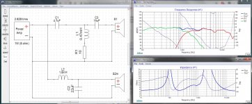
Based on the factory DXO file provided by @lousymusician ... here is a mod you may like to try.
It's based on the 3rd order model and it does a baffle step, of sorts, by slightly attenuating the tweeter and evening out the response a bit, without wasting any energy on new parts hooked to ground or using inline resistors.
Attachments
Last edited:
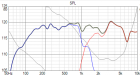
I used lousymusician's files to cross-check. Different results again, but there's always something to be gleaned. Thanks lousymusician, are these your own?
Comparing the stock crossover, to adding the 2.3mH, 5.2ohms, and 7ohms shows that the bass still doesn't reach well below 100Hz. I also think it shows you have good hearing regarding the tweeter. And maybe the 4k and up region shouldn't be falling away from 2k. Personally I go a little more as Douglas has, but the directivity of the waveguide plays a part and you are the judge.
Comparing the stock crossover, to adding the 2.3mH, 5.2ohms, and 7ohms shows that the bass still doesn't reach well below 100Hz. I also think it shows you have good hearing regarding the tweeter. And maybe the 4k and up region shouldn't be falling away from 2k. Personally I go a little more as Douglas has, but the directivity of the waveguide plays a part and you are the judge.
Attachments
Last edited:
- Status
- This old topic is closed. If you want to reopen this topic, contact a moderator using the "Report Post" button.
- Home
- Loudspeakers
- Multi-Way
- Need help: Adding BSC to passive 2 way Tannoy 12"