No. VC is not set up to do this kind of enclosure. Half-space option does not do what you think it does. Cabinet dimensions are to some degree the size of your wall, and to some degrees, other sizes. Your results are incorrect.STEP FIVE
Use the Diffraction tool to get off-axis SPL data for the two 6" drivers and two PRs as one unit. Enter baffle dimensions and driver locations from the second Excel sheet in step three above. For Half-space response, pick the TotalSPL file exported from the Enclosure tool above. This time, check "Fead speaker" to have off-axis files added in VituixCAD for you (the woofer needs to be selected in VC for this to work):
No, adjust excess phase? Where are you getting this?STEP SEVEN
Bring the SPL and Impedance files from SPL Trace into VituixCAD, and adjust the delay for the tweeter:
Note, I'm not 100% sure, but *I think* delay should be adjusted so that Excess phase plot generally follows or meets the Minimum phase plot.
Although you can manage delay with a passive crossover, it sounds as though you are reading a tutorial for an active crossover?
A passive radiator is very similar to a vent/port. Are you still thinking sound will be lost through your wall via the rear chamber?passive radiators
I disagree, you haven't given the optimiser enough to work with. This is not adequate.Here is a screen shot of the optimized design
I just modeled the same crossover that VC gave me in XSim. The tweeter side came out about the same, but not the woofer side. Very different. So I will do more research about how to more accurately model this thing. Mainly, I don't understand how to incorporate PRs in the design of the crossover, since these are obviously not powered by the crossover.

Examine the damping of your woofer highpass filter.
Your PRs are the least concern. Their response is so far down away from the crossover that you could almost get by without including them. When you do, their dispersion characteristics and their baffle characteristic are simple, and they are room controlled at this frequency anyway.
Your PRs are the least concern. Their response is so far down away from the crossover that you could almost get by without including them. When you do, their dispersion characteristics and their baffle characteristic are simple, and they are room controlled at this frequency anyway.
I was actually just thinking that... model the crossover without the PRs because anything they add is to the far left on the chart anyway. I just changed the XSim model with two drivers in series, and for spl and impedance profiles, used the frd and zma files from the data pack on Parts-Express. Adjusted the high-pass filter on the woofer and it makes more sense now. ")
I will want to circle back to VC and do the same, and then compare results. See what I see.
Also, any concern with the tweeter going to 16 ohm at 20kHz on the impedance plot? On that same chart, how should the phase plot look when adjusting components? What to watch for? Thank you!

I will want to circle back to VC and do the same, and then compare results. See what I see.
Also, any concern with the tweeter going to 16 ohm at 20kHz on the impedance plot? On that same chart, how should the phase plot look when adjusting components? What to watch for? Thank you!
I have no problem with the accuracy of VC or of XSim.I will want to circle back to VC and do the same, and then compare results. See what I see.
Expect correct results if... you provide the right data, you use the data in the correct way and you use the tool in the correct way. I also like to keep track of what is done automatically by the program so it doesn't surprise me with anything unexpected. That would be less welcome than a spell checker.
No.Also, any concern with the tweeter going to 16 ohm at 20kHz on the impedance plot?
Overall or from driver to driver. (Or are you referring to my earlier comments on excess phase?)On that same chart, how should the phase plot look when adjusting components? What to watch for?
Last edited:
I re-did the design in VC with just the tweeter and two drivers in series. No Enclosure or Diffraction tools. I used frd and zma files from parts-express for the woofers, and used the same traced files for the tweeter from the last config. Removed the zobel network because it was having no effect with this component combination. Here is how the optimized chart in VC looks, with updated crossover:

Copying this crossover to XSim, using all the same frd/zma files, results are very similar with I think some pretty minor differences comparing to VC. Here is the same crossover in XSim:

And here is a tweaked version in XSim to match the output closer to VC's. The second inductor on the woofer had no effect, which makes the design a bit simpler (3rd to 2nd order). What do you think?

I still need to understand excess phase and what the phase plot means. I don't know enough about this to ask any productive questions (yet).
Copying this crossover to XSim, using all the same frd/zma files, results are very similar with I think some pretty minor differences comparing to VC. Here is the same crossover in XSim:
And here is a tweaked version in XSim to match the output closer to VC's. The second inductor on the woofer had no effect, which makes the design a bit simpler (3rd to 2nd order). What do you think?
I still need to understand excess phase and what the phase plot means. I don't know enough about this to ask any productive questions (yet).
Cool. I am in two minds about this, given that the primary effect is not applicable to your enclosure, but some lesser effects may be partially present. If I were unable to build I'd create a special blend, but it is preferred to do the following. Sim without cabinet, take steps to reduce the effect with rounding and good design/dimensions etc, measure.No Enclosure or Diffraction tools.
It's a perfectly cromulent configuration, so it doesn't surprise me that you are finding it can work here.(3rd to 2nd order). What do you think?
Phase (as you showed) will normally be related to the response and its curves. If phase doesn't come up this way, the difference is excess phase. In this case it is likely due to diffraction which has added delay.I still need to understand excess phase and what the phase plot means. I don't know enough about this to ask any productive questions (yet).
You choose to either refine your acoustic design, or live with it.
So I've gathered phase is basically the time difference between current and voltage measured in degrees. 0 degrees is the most efficient, and you want to avoid 45 degrees which is the least efficient. But since tweeters draw less current, 45 degree phase in the 10-20kHz is not as bad as in woofer ranges where the current draw is much higher, and therefore puts potential dangerous loads on the amp.
So looking at the phase chart in VC, I'm not really sure how to interpret that because the vertical axis is -180 to 180, rather than -90 to 90.
Having said all that, I can see now that the proper way to design the crossover is really build the speaker and measure its response in the room it will be installed. This is done with REW and a good mic. Originally starting with limited knowledge in speaker/cross over design, I was hoping it could all be done in software, but really software is just a good starting point. VC/XSim/WinISD gives a good idea of which components will work for a particular box design/size. Next will be to build that box, and measure the output! Then feed those frd and zma files into VC/XSim to come up with the crossover. This should be interesting.
In a manner of speaking.So I've gathered phase is basically the time difference between current and voltage measured in degrees.
Ok, starting to run off track here. May I suggest you ignore the phase plot except where it comes to getting the woofer and tweeter to be working together.0 degrees is the most efficient, and you want to avoid 45 degrees which is the least efficient. But since tweeters draw less current, 45 degree phase in the 10-20kHz is not as bad as in woofer ranges where the current draw is much higher, and therefore puts potential dangerous loads on the amp.
360 degrees is full circle.So looking at the phase chart in VC, I'm not really sure how to interpret that because the vertical axis is -180 to 180, rather than -90 to 90.
No. With the exception that you have dedicated a wall to being a part of your speaker. You could test it on a large baffle instead. You don't want to include your room effects in the measurement.Having said all that, I can see now that the proper way to design the crossover is really build the speaker and measure its response in the room it will be installed.
Take a look at this. In this thread, mp006ltk is also doing an on wall design. His measurements include a fake wall, because the wall has become a part of the design.
Attachments
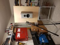
Perfect. This is pretty much my same scenario. And relatively easy to setup. Maybe put the whole thing in a tent of moving blankets? It will be some weeks still before I get to the point of actually taking measurements (recently moved, still need to setup shop to build enclosures, etc.) This is definitely the plan though.
- Status
- This old topic is closed. If you want to reopen this topic, contact a moderator using the "Report Post" button.
- Home
- Loudspeakers
- Multi-Way
- Which configuration?