Hi Guys,
So I'm about to build my first set of speakers and I wanted to run my plan by some more experienced builders to see if I've made any mistakes I'm not aware of before I actually throw money at it.
My plan is to build 2x 2 way speakers (woofer + tweeter) and an Sub enclosure.
It will be 100% passive with custom fixed crossovers
My speaker choices are as follows:
Highs:
Dayton Audio ND25FA-4 1"
Mids:
Dayton Audio RS125-4 5"
Lows:
Dayton Audio DCS205-4 8"
The Highs and Mids Enclosure is modelled after a Folded Voight Tube
with the Highs having a seperate airspace.
Will be building 2 of these long term.
The Lows are housed in a T-Line Box
I designed my Crossover(s) in Vituix with guidance from KirbyMeetsAudio's Video
Here's a photo of the overall frequency response + Diagram/Blueprint
I've sourced all the parts locally and should be ready to start but do you more experienced Builders have any insight/questions/ideas that would either help me be more cost effective (especially in the crossover) or things that would allow for better performance overall?
Thanks in Advance
So I'm about to build my first set of speakers and I wanted to run my plan by some more experienced builders to see if I've made any mistakes I'm not aware of before I actually throw money at it.
My plan is to build 2x 2 way speakers (woofer + tweeter) and an Sub enclosure.
It will be 100% passive with custom fixed crossovers
My speaker choices are as follows:
Highs:
Dayton Audio ND25FA-4 1"
Mids:
Dayton Audio RS125-4 5"
Lows:
Dayton Audio DCS205-4 8"
The Highs and Mids Enclosure is modelled after a Folded Voight Tube
with the Highs having a seperate airspace.
Will be building 2 of these long term.
An externally hosted image should be here but it was not working when we last tested it.
The Lows are housed in a T-Line Box
An externally hosted image should be here but it was not working when we last tested it.
I designed my Crossover(s) in Vituix with guidance from KirbyMeetsAudio's Video
Here's a photo of the overall frequency response + Diagram/Blueprint
An externally hosted image should be here but it was not working when we last tested it.
An externally hosted image should be here but it was not working when we last tested it.
I've sourced all the parts locally and should be ready to start but do you more experienced Builders have any insight/questions/ideas that would either help me be more cost effective (especially in the crossover) or things that would allow for better performance overall?
Thanks in Advance
Your Image links are returning: "{"status":"error","code":404,"message":"Invalid or unsupported image format. Is it a valid image?"}"
Best option is to upload them as attachments to the forum itself, that way they won't get lost if you ever change your online storage arrangements etc.
Best option is to upload them as attachments to the forum itself, that way they won't get lost if you ever change your online storage arrangements etc.


Cool, can see them now 
Handful of initial thoughts in no particular order...
(I'm pretty ignorant on TL's and Voight pipes so I'm not qualified to make any comment at all about them, these are pretty much just generic crossover design points only...)
You have no highpass for the mids - that will likely result in overdriving them and at least increasing distortion if not burning them out as you're effectively exposing them to the full bass content of the signal.
Your bass/mid crossover is very low - I know that that Dayton LF does recommend a low XO, but it results in the mid doing a lot of work (even with a highpass added) and requires very large component values - these are likely to be very big and expensive.
Taking those together, you may realise why it's quite common to use an active crossover and biamp if you definitely need to cross that low.
You appear (though I'm not sure what software you modelled the crossover in) to have included no DC Resistance for the inductors - that won't be the case in reality and should be modelled using realistic values before going further. This is especially relevant if you do go ahead with a passive low/mid crossover that low as the low pass inductor for the woofer will have the highest DCR.
Can't tell if you've included the effects of baffle step loss & diffraction in your models or not - looking at how the mid stays flat through its lower range I suspect not. In fact, it looks like you've used the basic FRD from PE/Dayton for the modelling - that means you may not be accounting for any effect the mid enclosure has on its response either. (Unless the Voight pipe guarantees that there is no effect at all on the response, as I said above I admit I'm ignorant on that?)
Also can't tell if you've generated those component values accounting for the impedance of the drivers or not?
HTH,
David.
Originally I did have a Highpass on the mids but I was unsure if I still needed it given that the enclosures are separate, I removed it mostly as a cost saving measure.
I'm guessing the Bass/Mid XO is so low because there's no Highpass on the mids so that can/will change, pretty sure the DCS250s effective high end is 200Hz so I'll aim for that (will double check specs).
The Crossover did have 2ohm resistance across the board, this was done to have a mostly flat response around 85db. . however these were removed for cost and near Identical responses at 90db . . didn't account for distortion, can re-add tho, its like 10 bucks worth of resistors.
And yeah I'm not too sure on the science on the folded Voight tube, there was a calculator somewhere that I plugged the Mids Sd and Fs into and it spat out the dimensions I needed.
The T-line is however all my maths (god kill me) so the internal wave from the sub is in phase once it leaves the port so that "should" be all good.
So in your opinion should I be looking for an active crossover?
ok so I redesigned the crossover after Davids input and this is what I got at the moment.
This setup is much more expensive mainly cause the 100uF Caps are like $40usd each but fingers crossed you guys can help me be more cost effective.
what I took into consideration during the design:
Highs Effective Range is 2,500-20,000hz
Crosses with Mids at 2,200hz
100% low fade out at 1100hz
High pass filter
Mids Effective Range is 65-5,500hz
Crosses with Lows at 200hz
100% low fade out at 72hz
100% high fade out at 5800hz
High & Low pass filters
Lows Effective Range is 30-200hz
100% High fade out at 450hz
Here's the revised SPL graph (does the dip at 2,000hz where the mids/high cross matter too much?)

and the revised Crossover (needs tweaking to be more cost effective)

Overall with this revision all drivers are within or very close to their usable frequency according to their spec sheets.
This setup is much more expensive mainly cause the 100uF Caps are like $40usd each but fingers crossed you guys can help me be more cost effective.
what I took into consideration during the design:
Highs Effective Range is 2,500-20,000hz
Crosses with Mids at 2,200hz
100% low fade out at 1100hz
High pass filter
Mids Effective Range is 65-5,500hz
Crosses with Lows at 200hz
100% low fade out at 72hz
100% high fade out at 5800hz
High & Low pass filters
Lows Effective Range is 30-200hz
100% High fade out at 450hz
Here's the revised SPL graph (does the dip at 2,000hz where the mids/high cross matter too much?)
and the revised Crossover (needs tweaking to be more cost effective)
Overall with this revision all drivers are within or very close to their usable frequency according to their spec sheets.
May be worth downloading Boxsim 2.0, this has an optimise function that does a half decent job of calculating the values once you get halfway there I.e. an initial starting point that is close.
Also worth checking the mid polarity, from the spl and those dips it looks like either the crossover points are too far apart on the roll offs or you have the mid at the wrong polarity.
I’m no expert but may be worth swapping the mid and tweeter polarities to get the crossover points adding not cancelling, only 4 options so worth checking which works best. Also iirc at the crossover points each driver should be at 6db down, yours look more like 10db which may be a reason for the dips, and I think you will hear dips that big, a dip of 3dB halves the energy getting to your ear so is very much perceptible.
Last edited:
Ok so here's where I'm up to,
I smoothed out the SPL Graph to get rid of the dips and made sure the crossover points are approx 6db down as Ugg10 mentioned.
I allowed myself higher uF values on the caps since I can source them as Electrolytyic caps for fairly cheap as Chris661 mentioned, replacing them isn't too much of a bother as long as they work.
I tried boxsim 2.0 but tbh its kinda hard vs Vituix to get working properly so I kinda dodged it, its still installed for another time.
Not real sure what you mean AllenB, I can tell Vituix to build me a High/Low pass filter at whatever frequency but it usually spits out stuff that needs tweaking anyway, the in-built Db level is 85 but I'm not sure how to change it.
As far as I can tell all my Drivers are in band and not interfering, I could be wrong tho.
Anyway here's the current SPL Graph and Crossover:
In your xo sims:
- you may be able to get away with just 2nd order electric on the woofer
- you must look at the individual driver phase not the overall system phase and then try to get good alignment between them in the 2 xo regions
- also try some resistors in the shunt to ground leg to both shape the knee of the rolloff and to manipulate individual driver phase. Not always necessary but it can be extremely helpful and costs you pretty much nothing.
Also, it's still not clear if you have included the box effect, baffle step and diffraction sims into each driver's frequency and impedance responses. These are essential to get something that is going to be close to real life. So too is including the correct acoustic center distances for each driver. Without these, your xo sims are not going to be correct.
And I think it's only fair to tell you that even if you do everything right, your sims may still be off from reality in some way or another. If you are not looking for perfection, this may be fine with you. But to be assured of getting the most out of your design, you really need to measure each of your driver's FR and Z responses as well as their acoustic centers in the cabinets.
Having said that, for a 2.1 setup, I would be using a receiver that handled the sub xo frequencies and therefore dispense with the need for the 3rd woofer xo filter as well as the HP filter on the mid - but maybe that's not possible for you. In that case, I think you need to be very careful about where you place your subs - just somewhere in the corner will totally change the phase alignments (ie timing) which will likely completely change how the subs and the midwoofers sum.
Fyi, VituixCAD has a crossover optimizer built into it. It's in the view menu at the top left of the window (not sure why they didn't put it in the tools menu). Might be worth trying out, just make sure to save before running it.
It also has the ability to account for room simulation, diffraction, baffle step, etc, so you can try those features out if you want. All in all it's my go to program for speaker simulation (along with WinISD for quick and dirty box modelling).
It also has the ability to account for room simulation, diffraction, baffle step, etc, so you can try those features out if you want. All in all it's my go to program for speaker simulation (along with WinISD for quick and dirty box modelling).
Ok so update time since its been a couple of days.
jReave:
I tried doing a 2nd order pass on the woofer but it wasn't getting rid of the unusable frequency fast enough so I opted for a 3rd order.
Driver phase seems fine, just had to tweak the xo to iron out the dips.
Not real sure what you mean with the leg and knee roll off, I figure it has something to do with the rate of frequency roll off but again, not too sure.
This speaker set up is aimed at being a portable solution so I get that where they're located in an environment will change their phase but as long as they're good in terms of Driver, Crossover and Enclosure, im not too worried about the rest.
ILikeFoodz:
I tried messing with the optimiser but honestly the changes it made to the last SPL graph I uploaded was so minimal I didn't bother saving it so I'm guessing I've got the crossover fairly well optimised without having to use the tool xD, good to know in the future tho thanks
Ok so there's all the Replies sorted, lets talk about changes.
I'm redoing all the enclosures since a couple of you guys mentioned that I have no simulations on how the drivers would behave in XYZ enclosure and the issue I came up with is there's bugger all programs that Properly simulate TL enclosures soooo I scrapped it. .
I'm Designing the Sub-woofer Enclosure after Brian Steele's Boom Unit which actually uses the same Driver as I chose (wooo I'm Lazy!.. Kinda), I changed some stuff for my one but its about 80% Identical to his.
besides I'm pretty sure he goofed some T/S values when putting it into Hornresp.
Here's the Hornresp Stuff for people who are interested.


Going to redesign the Mids/Highs Enclosure as well but soon tm.
was looking into D'appolito Designs and getting a couple extra Mid-Woofers.
Anyway that's where I'm at atm, I'll try keep this updated and reply to questions/ideas as best as I can
thanks for all the help so far guys
jReave:
I tried doing a 2nd order pass on the woofer but it wasn't getting rid of the unusable frequency fast enough so I opted for a 3rd order.
Driver phase seems fine, just had to tweak the xo to iron out the dips.
Not real sure what you mean with the leg and knee roll off, I figure it has something to do with the rate of frequency roll off but again, not too sure.
This speaker set up is aimed at being a portable solution so I get that where they're located in an environment will change their phase but as long as they're good in terms of Driver, Crossover and Enclosure, im not too worried about the rest.
ILikeFoodz:
I tried messing with the optimiser but honestly the changes it made to the last SPL graph I uploaded was so minimal I didn't bother saving it so I'm guessing I've got the crossover fairly well optimised without having to use the tool xD, good to know in the future tho thanks
Ok so there's all the Replies sorted, lets talk about changes.
I'm redoing all the enclosures since a couple of you guys mentioned that I have no simulations on how the drivers would behave in XYZ enclosure and the issue I came up with is there's bugger all programs that Properly simulate TL enclosures soooo I scrapped it. .
I'm Designing the Sub-woofer Enclosure after Brian Steele's Boom Unit which actually uses the same Driver as I chose (wooo I'm Lazy!.. Kinda), I changed some stuff for my one but its about 80% Identical to his.
besides I'm pretty sure he goofed some T/S values when putting it into Hornresp.
Here's the Hornresp Stuff for people who are interested.
Going to redesign the Mids/Highs Enclosure as well but soon tm.
was looking into D'appolito Designs and getting a couple extra Mid-Woofers.
Anyway that's where I'm at atm, I'll try keep this updated and reply to questions/ideas as best as I can
thanks for all the help so far guys
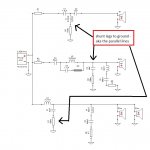
Not jReave, but the leg was referring to connecting resistors across the driver, whereas the knee was referring to the filter response as shown on the plot where it turns downward.Not real sure what you mean with the leg and knee roll off,
A picture might help. See attached (just some random 3-way I had saved).
Note the added resistors in the parallel legs as well. To see their effects, just add them to your modelling efforts and see what they do and whether or not they might be helpful in your situation.
Is the phase fine or does it "seem" fine. Maybe attach a pic with the individual driver phase so we can confirm their adequacy or not.
Still you have not mentioned whether you are including baffle effects and acoustic center info? Again, these are vitally important for accurate simming.
I also noticed the very large resistance on your woofer inductor. Lower that if you can by going with an iron core inductor instead of an air core. Quite a difference in cost and size as well.
Attachments
- Status
- This old topic is closed. If you want to reopen this topic, contact a moderator using the "Report Post" button.
- Home
- Loudspeakers
- Multi-Way
- First Build (did I mess up)