I have a pair of midrange AMT drivers I am wanting to make some wave guides for. They are good down to around 200hz but I will be crossing them at ~300hz. The drivers are effectively 50mm x 140mm the throat of the wave guide would be the same.
I have spent some time reading about SEOS wave guides and I feel this profile most suitable as I don’t really need to load the drivers. The challenge I have is I don’t really understand how to design a horn with a rectangular throat transitioning to an elliptical mouth. I see some examples such as the wave guides for the RAAL drivers “SEOS hORNS”, which look as if they have been cut in half and extruded to make the long sides of the throat.
I doubt there is a spreadsheet for designing such horns, a search has found spreadsheets for OSWG, but none for SEOS ones, never mind ones with rectangular throats.
Some guidance/pointers would be appreciated, on how to start.
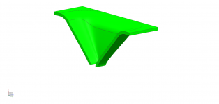
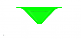
I took some inspiration from “mabat” notes for Ath4 on the use of superellipses. You can make a rectangular profile with an ellipse so I thought I would just transition from an N=10 to an N=5 superellipse between the throat and mouth. So here is my first attempt, for a 90 deg horizontal 40 deg vertical wave guide using Geddes OS profile. It’s 600mm wide. As I don’t have the mathematical skill to put the radius on the profile, I have done it in CAD with a 100mm radius.
Attachments

Thanks for that, the AST25120 looks a lot better with the back off. This gives me the confidence to proceed to writing the CAM files and firing up the CNC. Modelling things takes hours..... machining/making one takes days. What were the horizontal and vertical angles on the JMCL horn. Did you blend in the rectangular throat in CAD to an existing horn definition?
These midrange AMT’s are proportional less rectangular being 50mm wide compared to the AST’s which are 25mm wide, for a similar height, so the vertical dispersion should be better.
These midrange AMT’s are proportional less rectangular being 50mm wide compared to the AST’s which are 25mm wide, for a similar height, so the vertical dispersion should be better.
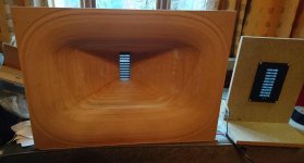
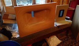
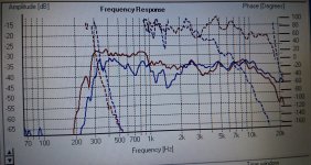
Finally finished making a “ test” horn. Carried out some measurements today too. Not a lot of horn loading, but wasn’t expecting this as the driver is an open back. The major difference is the off axis response where the response is almost the same upto 8k for 0 deg 30 deg s and 45 deg s. Needs some equalisation in the DSP, to level off the response. Positive outcome, need to integrate the driver into my set up to understand if this could replace the jbl2482’s for midrange duties.
Attachments
- Status
- This old topic is closed. If you want to reopen this topic, contact a moderator using the "Report Post" button.
- Home
- Loudspeakers
- Multi-Way
- Wave Guide for Midrange AMT