Im new to xover design and am presently familiarising myself with vituixcad.
To proceed I have done several exercises by inputting well proven design using data retrieved through vituixcad SPLtrace e.g bitfrost, tarkus and tons of others and they give expected near results with deep nulls. However I have some questions as follows:
1. On the DRIVER screen at the bottom box Delay, does input of a positive number means that the driver is further away from the listening distance or nearer?
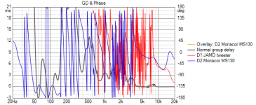
2.On the right screen on the chart Phase/ GD, why do I get many zigzags when I input my measured frd see attached png) which renders the phase matching impossible to understand , while when I input captured data from drivers charts by using SPLtrace, the phase_gd screen is easily interpreted. The left picture is mine input and the right one from seas bitfrost kit.
So you pros, how do you proceed to avoid all these phase zigzags when you input measured data.
tks to all. Alain
To proceed I have done several exercises by inputting well proven design using data retrieved through vituixcad SPLtrace e.g bitfrost, tarkus and tons of others and they give expected near results with deep nulls. However I have some questions as follows:
1. On the DRIVER screen at the bottom box Delay, does input of a positive number means that the driver is further away from the listening distance or nearer?
2.On the right screen on the chart Phase/ GD, why do I get many zigzags when I input my measured frd see attached png) which renders the phase matching impossible to understand , while when I input captured data from drivers charts by using SPLtrace, the phase_gd screen is easily interpreted. The left picture is mine input and the right one from seas bitfrost kit.
So you pros, how do you proceed to avoid all these phase zigzags when you input measured data.
tks to all. Alain
Attachments
Last edited:
Tks Zvu for re directing me . There is a lot to read , I think I have found the answer on page 100:
---------------------------------------------------
Originally Posted by kimmosto View Post
"If woofer's delay is entered as 0 us, tweeter's delay is positive 43 us (15mm).
If tweeter's delay is entered as 0 us, woofer's delay is negative 43 us (-15mm). This is better way."
For the ease of newcomers, I am of opinion that this piece of information should be displayed when the mouse is rolled over the Delay box.
and this also at post 548 on page 55
But it seems contradictory to the above!! or am I missing something that I do not understand.....
--------------------------------------------------------------------------
"Negative delay [us] in Drivers tab is equal to moving driver towards the mic or listener, and positive delay is moving further.
Negative Z mm for driver instance in the crossover is equal to moving driver towards the mic or listener, and positive Z mm is moving further.
Speed of sound is 344.0 m/s in VituixCAD."
Hi, not sure if I should post this since I don't have enough background data so this all might be wrong  Based on the thread at hand my opinion is as follows:
Doesn't seem to contradict, all there is to it is that negative delay = negative distance between reference point and the mic. Positive number = further from the mic. So, it all depends what you choose your reference plane, the number is a relation to that. Stuff that are further from the mic in relation to a reference plane get positive delay.
Quote from page 100 you posted appears to be out of context, it appears to be a comment to a question that is not shown here. We don't know how if the tweeter is behind of the woofer or the opposite. If we assume the tweeter is behind (recessed to the baffle), like in most of the speakers when the drivers are not in same plane, there is no contradiction.
Kimmosto seem to be talking about the reference plane on the baffle: If the woofer is the reference plane (and we assume the tweeter is recessed) the tweeter is +15mm/+43us to that reference plane, eg. it is further from the mic than the woofer. Woofer delay = 0, tweeter +43us.
One could choose to use the tweeter as reference plane instead of the woofer in VituixCAD, as Kimmosto suggest on the quote. Then the woofer would be closer to the mic than the reference plane (tweeter), so woofer delay would be negative. Woofer delay -43us, tweeter delay 0.
I think if you measured your speaker with suggested measurement setup (see VituixCAD measurement guide), the delays are already included in the measurements and driver delays can be left as 0.
Please refer to the manual and ask in the VituixCAD thread for proper help
I hope this was helpful! Peace
Based on the thread at hand my opinion is as follows:Doesn't seem to contradict, all there is to it is that negative delay = negative distance between reference point and the mic. Positive number = further from the mic. So, it all depends what you choose your reference plane, the number is a relation to that. Stuff that are further from the mic in relation to a reference plane get positive delay.
Quote from page 100 you posted appears to be out of context, it appears to be a comment to a question that is not shown here. We don't know how if the tweeter is behind of the woofer or the opposite. If we assume the tweeter is behind (recessed to the baffle), like in most of the speakers when the drivers are not in same plane, there is no contradiction.
Kimmosto seem to be talking about the reference plane on the baffle: If the woofer is the reference plane (and we assume the tweeter is recessed) the tweeter is +15mm/+43us to that reference plane, eg. it is further from the mic than the woofer. Woofer delay = 0, tweeter +43us.
One could choose to use the tweeter as reference plane instead of the woofer in VituixCAD, as Kimmosto suggest on the quote. Then the woofer would be closer to the mic than the reference plane (tweeter), so woofer delay would be negative. Woofer delay -43us, tweeter delay 0.
I think if you measured your speaker with suggested measurement setup (see VituixCAD measurement guide), the delays are already included in the measurements and driver delays can be left as 0.
Please refer to the manual and ask in the VituixCAD thread for proper help
I hope this was helpful! Peace
First you should make sure that the delay was correct when you measured. The amount of delay is not important but between the woofer and tweeter it should either be the difference at the listening position, or they should be the same and you add the listening position later. The first option is probably best.2.On the right screen on the chart Phase/ GD, why do I get many zigzags when I input my measured frd see attached png) which renders the phase matching impossible to understand , while when I input captured data from drivers charts by using SPLtrace, the phase_gd screen is easily interpreted.
Then, you can unwrap phase. You can add any amount to driver delay, as long as you do it to the other driver as well.
delay box entry in vituixcad
To get it clearer on this picture,if I take the tweeter as the reference plane, then the woofer being further away from the mic position/listener, the entry in the delay box will be positive : let's say +100us=3.4 cm . Please confirm if I'm correct.
To get it clearer on this picture,if I take the tweeter as the reference plane, then the woofer being further away from the mic position/listener, the entry in the delay box will be positive : let's say +100us=3.4 cm . Please confirm if I'm correct.
Attachments
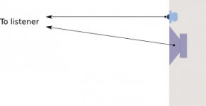
To get it clearer on this picture,if I take the tweeter as the reference plane, then the woofer being further away from the mic position/listener, the entry in the delay box will be positive : let's say +100us=3.4 cm . Please confirm if I'm correct.
Hi, not sure what you are going to do and I don't have too many hours on VituixCad, so please refer to VituixCad manual or ask in the VituixCad thread for pro help
Here is what i have understood: When designing a speaker crossover, build the speaker first. Measure each driver in the speaker separately rotating the speaker on a turntable keeping mic distance from the rotation center (the reference plane!) the same (on the 0degree, on axis measurement)and adjusting the microphone height for each driver center. I think the delay box comes to play, when all drivers are not on the common rotation axis!
In your picture both drivers seem to be on the same plane, the enclosure baffle, so delay box should be left 0 for both drivers if the baffle is used as the rotation axis. When you are in the crossover design window, it is there when you pick the listening position relative to the speaker enclosure by setting x axis position for the drivers (or was it y axis
, height). Listening distance is found from the options if I remember and listening angle is somewhere as well. As in you picture the tweeter is left at height 0 (listening axis, ear height), bass driver below would get center to center distance to the tweeter, a negative value for the x. That could be -12cm for 1" dome and 6.5" woofer or what ever your implementation is. Ear height could be above the tweeter or between the drivers, just adjust the x value for each driver accordingly. VituixCad shows curves at the listening position, so the delay to listening position in your picture is automatically included in the results.
All above is from my memory with limited knowledge so please verify from the manual
Vituixcad is very capable tool, you only have to tell it what your measurements represent. Do it like in the manual andall should work just fine
Last edited:
Yes, like your drawing (well almost, see below). Don't put anything into VC for delay, distance etc. The delay is already in your measurements.
Next you can put the same delay into each driver, they still keep the difference. You can unwrap the phase for both drivers at the same time. One will unwrap before the other, you must leave this difference.
Where you measure from. Try calculating the distance difference at the listening position, then find a place to measure that keeps that difference.
Ok tks. Now I need more simple explanation about phase use. I must admit I have no scientific background, I am a product of arts and humanities, as I always hated maths and physics at school.
I have gone through the REW help and through this thread " minimum vs real (unwrap) phase in ARTA", but still everything seems greek to me.
I am still dubious know how to proceed as regards phase .
Can someone guide me and list the sequence on Control screen in order to issue a workable FRD containing the correct phase for xover modeling.
Attachments
Last edited:
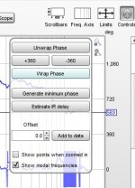
One way to do it.
Find your mic position and leave it there for the whole time. Take your tweeter measurement. Considering the image you just posted, change the delay setting until the tweeter phase goes horizontal at the top end. Remember this amount of delay and use the same amount on the woofer, no matter even if it wraps.
If you choose unwrap phase for the woofer, it will still be the same, the delay will still be the same, it will just look different. The phase will keep going down rather than beginning at the top again. When you export this, I think Vituixcad will find it easier to work with.
This is important, and I am not familiar with REW, does REW keep the timing right between measurements? With some systems you need to measure with two channels to make sure it is right. With some systems you need to adjust each measurement to set the starting time.
- Status
- This old topic is closed. If you want to reopen this topic, contact a moderator using the "Report Post" button.
- Home
- Loudspeakers
- Multi-Way
- Vituixcad phase and gd screen