Thanks in particular to Earl Geddes, BButterfield and FoLLgoTT, also to several people who've posted about MEH designs, though ultimately I could not find an MEH that suits.
For a decade GedLee Harper speakers were my mains, with various (sub-)woofers. This arrangement gave years of pleasure - thanks to Earl, twice over. I bought the Harpers as the Abbeys and Summas were beyond my reach, with a plan of later upgrading to larger GedLee speakers (bad plan as it turned out).
Background: I use a computer for playback, and am content with running convolution filters for crossovers, and very limited room correction at LF, etc., and am familiar with relevant theory (physicist). I also have DCX2496s. I agree with Earl Geddes about the trouble arising from trying to fix acoustic problems electronically.
I've considered options to replace the Harpers to obtain directivity control down to lower frequency, i.e., an extra octave roughly, as Summas would have yielded. I've also considerd narrower vertical directivity to avoid floor and ceiling reflections in my relatively low-ceiling room. That these qualities are not essential allowed me to be content with the Harpers. Designs and ideas that I considered include large conical MEHs; Taipuu-like large-fronted co-ax speakers; Grimm LS-1 shaped speakers, but with a "more-coaxial" layout; and various arrays. For some of these ideas I built prototypes or test baffles, including some MEH before I got the Harpers.
I rejected conventional co-ax designs due to throat problems - I tried a few experiments at correcting reflections in an old B&C drive - not bad, but really hard to get better than the Harpers (measurement or listening) and it would really need to be a 15" or a coax with an array of other emitters round it. I wonder if I ever hear the Taipuu speakers or similar will I be surprised?
My attempts at conical MEH were killed by what I later came to understand as HOMs. My conclusion was that throats must be OS, and ports are tricky. I considered learning 3D printing for a throat section, but rejected that, and I cannot find any commercial waveguide solution to modify.
I'm not sure a waveguide solution is possible, given the desire for vertical directivity - "pattern flip" is unacceptable which rules out almost everything, except a very few options e.g. XT1464, which is rather narrow horizontally ... Moving to a house with higher ceilings, and fitting modifiers is out of the question.
Progress picked-up when Horbach-Keele arrays came to my attention, and shortly after that FoLLgoTTs excellent design
Pseudo-coaxial with narrow directivity (and Horbach-Keele filters)
Fortunately, I read (enough) German and spent a while considering and simulating this approach. My new speakers benefit hugely from that. I was, however, unsatisfied with the side-woofer idea, and general box shape, having convinced myself that wide baffles should work better, and could never quite find the right solution.
I was circling around this when I first read BButterfield's thread* Fractal Array Straight CBT with Passive XOs and no EQ and this immediately started to open up opportunities, though again the final speakers are not copies of his "prototype" described elsewhere (not linked on this site by him for some reason, so I won't do so either, but not too hard to find), even if at a quick glance they look quite similar.
I desgined and built wedge-shaped speakers: 172cm (h), 66cm (w). The wedge is from about 6 to 14cm deep, with the outer edge larger and rounded. The driver layout is more symmetrical than BButterfield's design with the "centres of mass" of the tweeter, and upper-mid and lower-mid arrays aligned (co-axial, though that's a minor tweak indeed). I also put all the voice-coils in a plane.
The tweeters are AMTPRO-4 in waveguides not unlike FoLLgoTT's, but made from wood filled with modelling "clay" (DAS) using a crude custom shaper, not CNC. The AMT has a highly damped rear enclosure.
The six upper-mids are Peerless TC7FT04-04. They sit behind holes in the baffle that forn low-pass acoustic filters. With a bit of DCX2496 correction, these filters dominate the crossover. The Peerless drives are more sensitive than FoLLgoTT's choice, and were readily available. I went for an asymmetrical layout (three not four pairs - somewhere between the two sources of inspiration). There's a complicated box enclosing the upper-mids and the AMT enclosure. This is also braced to the back (with some lossy compliance for damping).
There are six Peerless FSL-0512R01-08 distributed according to the "fractal array" principle, taking up most of the baffle height. These are conventionally flush-mounted, and the baffle thickness of 30mm puts all 13 voicecoils in a plane. I did not add the extra mid-bass drivers right at the foot of the baffle, as seen in BButterfield's solution, but then was not aiming for as low a cutoff frequency. The main volume is connected, with a bit of lossy-bracing here and there.
I already had separate 12" woofers (old Precision Devices PD12SB30) to go with the Harpers, and these are now repurposed in sufficiently-shallow boxes that sit against the wall just "outside" the main speakers (which sit tight against the wall). The mains are about 1.5m from side walls and about 3.5m apart.
In terms of min-phase filters and delays, a DCX is used to tweak the various subs and woofers and another is for the crossovers. The four (sub-)woofers basically run flat, with some small delays/phase adjustments, most of the work was in finding the right places to put them. So, ignoring detail below 100Hz - entirely room dependent, the crossovers are at 130Hz, 800Hz and 2.8kHz, inspired from the BButterfield arrangement (i.e., min-phase filters for min-phase drivers, with very little EQ). The directivity is intended to be gone by about 250Hz where the array is one wave tall tapering to up to the narrow vertical CD by no more than 750Hz.
I'm still working on minor tweaks of the crossovers while looking at lobes and reflections (my target is 10dB down for anything at all bad radiated over any important range of angles as measured at the listening zone). I am not disclosing them in detail as that would be pointless. Almost all the information that would be needed is given by BButterfield in any case.
Based on impulse measurements, the result meets my goals, at least broadly. Initial measurements suggest that floor and ceiling reflections are reduced by about 10dB at least in the upper-vocal frequency range and above. Side-wall reflections are delayed over 3m and look relatively neutral (measurements continuing). That's not as much delay as with the Harpers, but the directivity is controlled to lower frequency so the reflection is cleaner over the band. The response on/near the listening axis is as desired, without unjustified corrections - there's a min-phase notch for the Helmholtz resonators on the upper mids and some gentle correction of the AMTs above 8 kHz, that's all so far.
The speakers are driven actively in the four bands, with the drives wired in sets to achieve impedance of 3-5 ohms for each input (three parallel pairs, two parallel triples and the tweeter). Consideration of voicecoil thermal mass was important for low compression, even though these very sensitive speakers won't ever be fed much power at all, I was scared to lose the benefits of the B&C drives in the Harpers - six 91dB (1W) drives with 1.2" VCs should do well enough above 130Hz (drives working coherently): more thanks to Earl.
For completeness, there are two 12" woofers, a 12" subwoofer (commercial BK Electronics) and a 3m long 15" closed subwoofer with built-in Helmholtz resonant low-pass filter (kills high order HD). That started as a tapped horn, but I could not brace it well enough to kill a couple of bad resonances on harmonics that were audible at times.
The Harpers now take surround duties in the rear room corners, used for a few suitable recordings (20-30m delay seems reasonably convincing with old church/cathedral sounds, for example). The main amplification comes from Hypex UcD (a mix of 180W and 30W) and a couple of other cheap class D chips for the surrounds and 15" sub.
It astonished me that, after only a little refinement, the tonal impression was rather similar to the Harpers, differences are mainly in the "imaging" - that's so recording dependent that I won't even try to describe it, beyond saying that many recordings work better and a few definitely don't! As measurements suggest, there's less "room" with most recordings. Further comment would be pointless, but I agree with some of the impressions recorded by BButterfield and friends, elsewhere.
If this (rather long) post, is seen by those whom I thank, I'll be more than happy. If it inspires someone else to follow their ideas and have as much fun, and some frustration struggling to find the right design, that's a bonus.
I won't post in-room measurements (need too much interpretation), and these speakers won't be moving outside, ever. I won't post crossover details, at least until I've done very many more measurements. I'm spending too much time listening to music for that to be any time soon.
I kept a couple of alternative designs in reserve, but these don't fit with BButterfield's suggestion - to avoid reflections from the rear (aka front) wall: "baffles should be much wider than the front is from the wall behind", so unless I start a wall-building project, that's the end for a while.
Ken
*apologies for the error in this URL as originally posted. I hope now corrected.
Last edited:
Photos as requested.
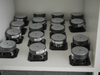
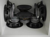
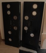
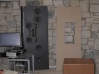
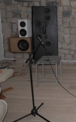
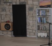
Here's what I could find from the photos during assembly, and early testing.
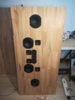
Photos show the upper and lower mid drivers, waiting impatiently to be assembled; the baffles during fabrication (two layers of MDF bonded) a back view of the left speaker during wiring , back still off, also, there's a hatch in the back to permit access to upper mid and tweeter internal enclosures and wiring; the same speaker during early testing for phasing etc., and a near-finished view. Still work to do at that point, and not in final location, but already sounding fine.
Ken
Here's what I could find from the photos during assembly, and early testing.
Photos show the upper and lower mid drivers, waiting impatiently to be assembled; the baffles during fabrication (two layers of MDF bonded) a back view of the left speaker during wiring , back still off, also, there's a hatch in the back to permit access to upper mid and tweeter internal enclosures and wiring; the same speaker during early testing for phasing etc., and a near-finished view. Still work to do at that point, and not in final location, but already sounding fine.
Ken
Attachments
In the context of a flat baffle, as opposed to a Danley-style PA horn, I don't understand the application of (such as) the untized waveguide (UWG). The waveguide size does not support directivity much below the cutoff of the drive one could put at the apex (e.g. a compression driver down to 800 Hz or so). For me, the mids are too close together to obtain the directivity I want Sure they allow the use of a dome tweeter, but I don't see the advantage of such a small voice-coil in the first place.
Also, as I see it, by putting the UWG at the middle of a fractal array, the horizontal and vertical directivity would end up almost the same. That's why I ended up with the AMT, it (or a ribbon, or very complex phase plug) is almost the only solution that "seeds" the V/H directivity ratio that can then be extended down towards the Schroeder frequency.
Of course others need not share the objective (especially if their house has higher ceilings with suitable treatment).
edited to add: the fundamental problem I have with any waveguide is they have to be round (ish), otherwise there's pattern flip - killer. So really the only solutions are the (excellent) ones from Earl.
Ken
Last edited:
Apologies for the jargon - was trying to be succinct ")
MEH: a Multiple Entry Horn representing the intellectual property originating from Tom Danley. Strictly, mine were always DEH (dual).
I like the term MEH as it expresses some of the frustration I had trying to get one to work perfectly due to HOMS (higher order modes within a region of space with impedance transitions at its boundaries - AKA a conical horn). "Meh" is also a surprisingly good description of how they measured and sounded on close inspection (likely due to my limited skill or excessive pickiness in setting requirements).
Ken
What would you change if you were starting from scratch again?
Thank you, that's a good question.
The drivers were on clearance, so even cheaper than expected, but see below.
Unless I come across a problem that can't be fixed, I'm sticking with these for a while. For several years I've understood that wide baffle - against the wall solves a problem (as might in-wall mounting, with a suitably-profiled wall).
I can't find other designs, of a level of complexity suiting my skills, giving the desired horiz/vert directivity and I'm reluctant to modify the 2.35m/93 inch high ceiling. So that leaves driver choice.
Best (surprisingly): the FSL-0512R01 is well matched to the task. Cloth surrounds, the motor/cone/suspension suits the job. They measure well in the limited bandwidth (better than the spec sheet), and are a better fit than the Faital Pro units I also considered. Other PA driver solutions would be around six times the price for little gain (except the potential of ear-splitting volume, which is not needed).
OK: TC7s ship without sufficient protection, in bubble-wrap and several had dented surrounds. I tried other samples from a few suppliers and they were all the same, I think I bought 20, returned the worst, used a couple only for test fits, and kept a few as spares after pushing out the surrounds. In future, I'd either buy a full outer packing or choose another option, but these are sensitive (88dBspl 1W, 1m) with a 19mm coil, a very smooth response, shorting cap, and were remarkably cheap.
Unsure: Is the AMT exactly the right solution? That they cost the same as the total of the other 12 drivers per main speaker is not a problem. I'd wanted 3.1 to 4:1 V:H ratio, and about 1" wide, and these are the closest I could find "off the shelf". The added waveguide flattens the response at the listening axis. Horizontal narrowing above about 7kHz is acceptable to me. The AMTs are not at all stressed in this design with around 96dBspl (1W, 1m) with the WG (1-3dB mid-band "gain"), and with the acoustic crossover around 2.8kHz. When writing this, I saw that there's now no EQ - after more measurements (there was some around 8kHz but it seems not to be needed). A 3D-printed waveguide would be neater.
Ken
Thank you. Hopefully those whom I cite/thank would also help.
I made these to fit particular locations in one not-very-large room of a particular shape, after listening to Harpers in almost every practical location within that space for almost a decade. Within similar constraints it seems to be a reasonable solution.
Ken
I made these to fit particular locations in one not-very-large room of a particular shape, after listening to Harpers in almost every practical location within that space for almost a decade. Within similar constraints it seems to be a reasonable solution.
Ken
Mk II
After some more simulation, and with the aim of building a "Mk II" that looks a bit more attractive (than twice 12 square feet of black cloth), I decided to make a second version. The basic design is of a thin, wedge-shaped speaker.
a) slightly shorter, at 130cm, now I can stand them on top of the 12" woofer boxes, an obvious option that I’d unfortunately missed the first time round
b) the mid-bass array is therefore about ¾ as tall. Now four drives provide close-enough spacing to control vertical lobes reasonably well. They are Peerless SDS-135F25CP02-06 - wired series-parallel to give 6 ohms. UK folks: CPC: Farnell is clearing out Tymphany/Peerless stock > relatively cheap.
c) I traded some "fractal" symmetry for uniformity of the array. Horizontally there’s little difference in the simulated response. In vertical, the more-uniform drive spacing on the mid-basses than Mk I leaves one dominant pair of lobes. The spacing and crossover were adjusted to keep those under control given the main floor/ceiling reflectons (with the proposed listening distance).
d) The "diagonal" responses are rougher than with the 6-driver array, but I did not find a set of angles where that would be a big problem at the main listening zone. I don’t believe this was a major compromise.
e) the upper-mid array is four TC7. This time they are placed conventionally on the front of the baffle without Helmholtz LP filters. That avoids the need for a notch at the 2nd (7kHz) mode of the cavity which was high Q and frees up choices for the crossover to the tweeter array (see below). The minor penalty is the need to dial in a few mm of delay to compensate for the difference in depth.
f) I made an array of five tweeters rather than using the AMTs. This took a while to figure out and was the enabling step for Mk II. Five BC20SC15-04, with much of the plastic surround cut off, allow close centre to centre spacing. These neodymium magnet tweeters have moderate sensitivity yet with small-diameter motors (under 30mm dia.). The array length is 145mm, c-2-c on the outer tweeters.
g) the tweeters are driven by one amplifier (I would have resorted to an extra active channel, but would have required a third DCX and more power amplifiers so tried first without). The outer four tweeters are wired series-parallel to give 4 ohms, matching the inner tweeter.
h) in a few iterations of trial and error I came up with a first-order passive crossover between the four tweeter array and the super-tweeter - giving a lot of overlap. The effective crossover, on axis, is at about 5 kHz. I ended-up with 10 uF in series with the supertweeter. I unwound and rewound the series inductor for the outer tweeter array, all the while tweaking the digital filter on the tweeter channel to reach a quite good response on and off axis. L is about 0.3 or 0.4mH. The array fits together more easily and smoothly than I expected, so I’m glad I tried this compromise rather than adding two more channels. I should perhaps simulate what I've donev - I don’t quite see how it works the way it does.
i) interestingly, the speakers measured almost the same with or without the back fitted (they sit against the rear wall). The array crosses over to the 12 inch woofer at about 140 Hz.
In conclusion, there’s a lot of fun to be had in searching for speaker designs based on arrays (fractal or otherwise). By combining several small drives, such that they have increased directionality there are plenty of advantages: the coherent addition on-axis means high sensitivity (in the region of 100dB 1W 1m), the heat is distributed over several voice-coils, reducing compression to levels that otherwise would need good PA drives, but the frequency responses can be very smooth in the relatively low range in which the drivers are used (large array: lower crossover). Even a “four-driver per stage array” can give relatively smooth off-axis response (as “Patrick Bateman” is currently observing on his contemporary array experiments). There’s scope for people to invent new and probably much better array geometries (perhaps even more small drivers, possibly a pseudo-random arrangement to smear lobes, etc.).
Attachments
The total driver price is really reasonable. I would be really interested in seeing the simulated/measured directivity plots. Edit2: While re-reading, I saw your notice that you will not post measurements because of interpretation needed. I fully respect that. I still kind of cannot grasp the concept of directivity control by arrays and maybe seeing directivity plots for this particular arrangement might help a little.
Let me ask one more question - which tool do you use for array simulation? Thank!
Let me ask one more question - which tool do you use for array simulation? Thank!
Last edited:
Simulation
There was a mixture of different simulation techniques done intermittently over a long time, with inspiration from those whom I cited in the first post. Other than the AMTs everything was very cheap, so at some point last summer, I decided just to start building. I based the second version on measurements from the first version and of the tweeters, rather than (much) simulation.
To work out basic array performance, I used some scripts to find the superpositions in 1D, in particular at angles corresponding to the first reflections - inspired by the general principles set out in Horbach-Keele.
Tolvan's "The Edge" helped with simulating the edge diffraction.
VituixCAD is good: I should probably have done much more with that and figured out a proper design with fully worked-out crossovers, but wanted to cut wood rather than spend even more time in front of a computer.
A lot of the time over the years was taken up searching for a waveguide based solution for the highest frequencies. I saw that FoLLgoTT did very well with the AMTs and I got an "acceptable" match with the rest of the array. However, there are a lot of important resonances to deal with compared to dome tweeters. For a while I had one of each version running, which was interesting, but I won't state a conclusion.
You wrote that you are planning to combine the unitised waveguide into an array, I'll be watching to see how that works out. If I was willing to set up a 3D printer, I'd probably look again at ways to cover perhaps 2 or 3kHz up with some kind of waveguide. I've no idea how it might look, but I think I'd be forced to broaden the vertical dispersion.
Regarding measurements, as I recall, it was comments elsewhere by BButterfield that helped me realise that I could extract (hopefully) enough information from some messy in-room results, rather than proper free-space measurements. This involves a mixture of incoherent (averaged pink noise) response measurements and using Holm Impulse with lots of moving the microphone and time window about trying to figure out what was direct and what reflection. Anything I could show without spending a lot of effort would be mostly "room".
Ken
Room measurements would be fine, I also do only in room measurements. The UICW ended for now in a simple box with a 15" woofer and still waiting for throughout testing. The results are very promising so far and therefore my next project will be a two way unity horn partially using 3D printing.
Your speakers are interesting for me for another reason now. There is no way I could fit a large enought waveguide into my smaller listening room, which is ca 3.7x3.3 meters. So i am considering alternatives with controlled directivity. I do not know if that would be even possible or make sense in such a small room. Now I have a pair of full range Lowther equipped Hedlund horns with a subwoofer there. That sounds really great, but the sweet spot is kind of narrow. Surprisingly enough, the Lowthers measure almost flat at the listening spot very slightly off axis.
I am not brave enough to try a full scaled line array, so I was looking at different sparse array techniques for corner placement and also your speakers should be possible to be placed in my room. If I could get 90 degrees or less horizontal directivity, placement near corners should not be a problem I think. I also have up to 8 DSP/amp channels available.
As I see it, another option would be an omnidirectional speaker and I was very happy with Claudio's 34c9 MDD speakers (My 34c9 (omnidirectional full range with 3FE22) build), but if possible, I would like to have more sensitivity and SPL available.
MaBat's ATH software can design a waveguide with given pattern control and I would consider using a dome/ring tweeter in a waveguide. I think a 2kHz waveguide could be relatively easy to design and print.
Last edited:
Update for completeness. About four months ago, following measurements of the two tweeter solutions (AMT vs short array), I swapped in the AMTPRO-4 as used in the original version.
Having listened to these speakers for a while, pondering what their best features are, my suspicion is the supression of the rear radiation and reflection matters at least as much as the floor & ceiling reflections. Offered as a hypothesis.
Previously, I've been happy with speakers far from the rear wall. Using wide-baffled speakers that are shallow, keeping the baffle close to the wall, appears to provide another approach. (Close to wall mounting.)
In my ~2:1 dimension room, the new approach allows good separation of side-wall reflections. I'm happier in this respect with the best I could achieve with Harper loudspeakers firing along the long dimensions, strongly tilted-in.
The open question at the point I reached four months ago: does the narrowed and only moderately uniform vertical dispersion intended to reduce floor and ceiling reflections provide any real advantage?
Noting that I had material left over from the above work, I thought for a while how to make speakers with the following design elements: 2"/61cm wide baffle, up to ~4"/10cm deep (no wedge, as I find baffle parallel to wall works well in my room), reasonable symmetry of radiation in all planes, hence a coaxial approach.
I'll describe the result of playing with this idea next.
- Home
- Loudspeakers
- Multi-Way
- After a decade of planning, thanks to forum members