I was talking about the unity patent: US6411718B1 - Sound reproduction employing unity summation aperture loudspeakersWell I've just read the patent( for about the 10th time ) and I still couldn't find any reference to 1st order slopes.
I found references to non integer slopes and roll offs that were 'non constant' slopes.
- Google Patents
andThe described embodiment also complements the phase shift, and in effect the time delay, caused by typical crossover filters. By placing the crossover frequencies such that the acoustic phase shift between the higher and lower drivers and the electrical phase shift in the crossover is approximately equal to the phase shift (delay) in the air path, the outputs from the higher and lower drivers combined in phase. The crossover filters utilized are typically either passive or active so as to produce a 90 degrees phase shift between the high and low frequency outputs, at the crossover frequencies.
The acoustic amplitude and phase measurement will allow “fine tuning” of the individual passive components in the crossover to partially offset the fact that each acoustic system is a bandpass filter and have some residual reactances not completely swamped by acoustic loading. For this reason, designing each band to be somewhat wider than needed (reducing that segments “extra” reactance) generally results in crossover values closer to straight theory. Unlike current art which depends on steep, high order crossover slopes and electronic time delays to avoid interference, all the drivers in the pyramid system discussed in the present embodiment are highly coupled to each other and generally a first or second order crossover gives the best results to date. Consideration of the amplitude, phase and acoustic impedance of all the elements involved is needed to realize the proper crossover. Until the recently, however, the equipment to measure this information has not been generally available.
That is exactly what I am saying, except that the overall response has to be affected by the crossover, but we design it to be flat summing.My thinking is that the on-and-off axis response, the pattern, will be more governed by the synergy horn size and wall angles, secondary flare, etc.
My point here is that many crossovers (LR4 & cie.) do not have flat power response, yet they have flat design axis response. This is because there are nulls off-axis that make the total acoustic output sum to less than away from the crossover point. That is what the LR XO is trying to solve: the bump on-axis due to the increased directivity.And not so much effected by x-over order and how it might change particular loadings away from xover freq.
Interesting idea that loading might be effected....I guess it has to, to some degree? thx !
In the case of a unity horn, the constant directivity would make such a crossover, when designed per the theory, display a drop in the response around the crossover. However, this is somewhat masked by the fact that the two driver operating together at the crossover can increase the radiating efficiency. So, less power is applied, but more gets out than would be expected from electrical summing. Of course, in real life, drivers have a response of their own on top of the one from the horn, so it is not as simple.
My reading of the Synergy Patent crossover description is just that it isn't a classical "SomebodysName-Worth" shape, but is designed essentially iteratively rather than mathematically for the overall target response of all the parts. Pretty much like what works best for nearly every other type multiway system. The thing Synergy or Unity brings is that you don't have to deal with off-axis driver interference since it behaves as point source. Get the on-axis right, the off-axis is right too.
Hi Bill,
I wasn't going to post this here as it seemed off topic but it now seems relevant..
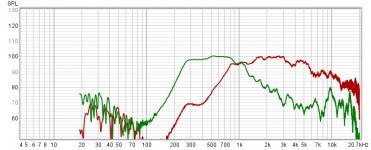
I was looking at the raw response of my mid / tweet combo on my project and it reminded me of the linear phase slopes on the miniDSP website.
Could the original synergies use a similar slope ? It fulfils the 'non constant' roll off slope in the patent. I remember a post from Tom D about the phase being at zero well above the low knee on the higher driver, which was why he chose the BMS CD.
Cheers,
Rob.
I wasn't going to post this here as it seemed off topic but it now seems relevant..
I was looking at the raw response of my mid / tweet combo on my project and it reminded me of the linear phase slopes on the miniDSP website.
Could the original synergies use a similar slope ? It fulfils the 'non constant' roll off slope in the patent. I remember a post from Tom D about the phase being at zero well above the low knee on the higher driver, which was why he chose the BMS CD.
Cheers,
Rob.
Attachments
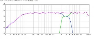
I've developed many MEH crossovers over the last twenty years and on many occasions noticed an interesting effect. I used to use CALSOD for my crossover development and occasionally the optimizer would snap to a solution like the one above and would have a very flat phase response. For a while I considered it an anomaly but once I worked out this behavior was beneficial I found it difficult to replicate. I am now of the belief that some of the Synergy crossovers sum through a plateau that is one or more octaves wide. I've not measured the acoustic response of a Danley Synergy horn to confirm this but at the moment I believe it to be correct.
Also to add to the discussion, many of my crossovers end up with no LP on the mids but will always have one or two notch filters often with one out of band, for the mids. A compression driver HP crossover and eq are usually quite a bit more complex but a MEH crossover for a system using a small dome tweeter can have quite a low parts count.
Also to add to the discussion, many of my crossovers end up with no LP on the mids but will always have one or two notch filters often with one out of band, for the mids. A compression driver HP crossover and eq are usually quite a bit more complex but a MEH crossover for a system using a small dome tweeter can have quite a low parts count.
Last edited:
My reading of the Synergy Patent crossover description is just that it isn't a classical "SomebodysName-Worth" shape, but is designed essentially iteratively rather than mathematically for the overall target response of all the parts. Pretty much like what works best for nearly every other type multiway system. The thing Synergy or Unity brings is that you don't have to deal with off-axis driver interference since it behaves as point source. Get the on-axis right, the off-axis is right too.
This has come to be my take too, on the last synergy/unity patent.
(And imo, not really anything all that new vs the earlier patents.)
Also agree with idea that get on-axis right, and off-axis will be too.
Other than perhaps for pattern flip, if width to height ratio is too high and without a secondary flare.
Yes it essentially does say that, but that won't necessarily get you linear phase with a passive XO. I fail to see the difference from the Unity patent if its limited to that. You can still design it mathematically with a few measurements, it still is a (mostly) linear system after all.My reading of the Synergy Patent crossover description is just that it isn't a classical "SomebodysName-Worth" shape, but is designed essentially iteratively rather than mathematically for the overall target response of all the parts. Pretty much like what works best for nearly every other type multiway system.
That is what I was trying to say earlier, this seems to really be the big win.The thing Synergy or Unity brings is that you don't have to deal with off-axis driver interference since it behaves as point source. Get the on-axis right, the off-axis is right too.
By the way, its off-topic, but do you know how well Xsim fares on wine? I already coded everything to do my horn enclosure simulations as I had a mac... I was planning to do it again for crossovers, but Xsim seems really good with a nice GUI and the possibility to apply on measurements. I could save myself a fair bit of work!
")
Hmm, good to know! The acoustic/mechanical roll-off in my prototype ends-up quite steep already. Nice to know you can do without in practice.Also to add to the discussion, many of my crossovers end up with no LP on the mids but will always have one or two notch filters often with one out of band, for the mids. A compression driver HP crossover and eq are usually quite a bit more complex but a MEH crossover for a system using a small dome tweeter can have quite a low parts count.
For posterity, I thought that adding a link to this thread I found was worthwhile. It seems what I was thinking of doing initially has been done in
Synergy build with TF0410MR mids - Page 2 - diyAudio
However, as theorized before in this thread, this only seems to work on a small bandwidth as the HornResp sims in that thread already shows the effect of standing waves in the "pre-horn". It won't be good up to 1-2kHz.
On another front, as mentioned by Patrick Bateman in horn, bandpass, horn, synergy? it seems that the impedance discontinuity of the port can be irrelevant if its thickness is small enough. This is even pointed out in Olson's book. So, the initial idea of this thread might be doable if one uses entry holes to the main horn that are very thin (say, made of metal).
However, even though the impedance discontinuity will become irrelevant to the fundamental 1P mode of the horn, I am doubtful as to how well that will turn out once the horn is used above the "cut-in" point of the higher order modes. One could expect that such a constriction in the middle of a horn could appear as a gigantic impedance discontinuity for these higher order modes.
Ah! The problem in this thread's name turns out to be more challenging than I thought!
- Status
- This old topic is closed. If you want to reopen this topic, contact a moderator using the "Report Post" button.
- Home
- Loudspeakers
- Multi-Way
- Increasing loading of midbass in synergy horn