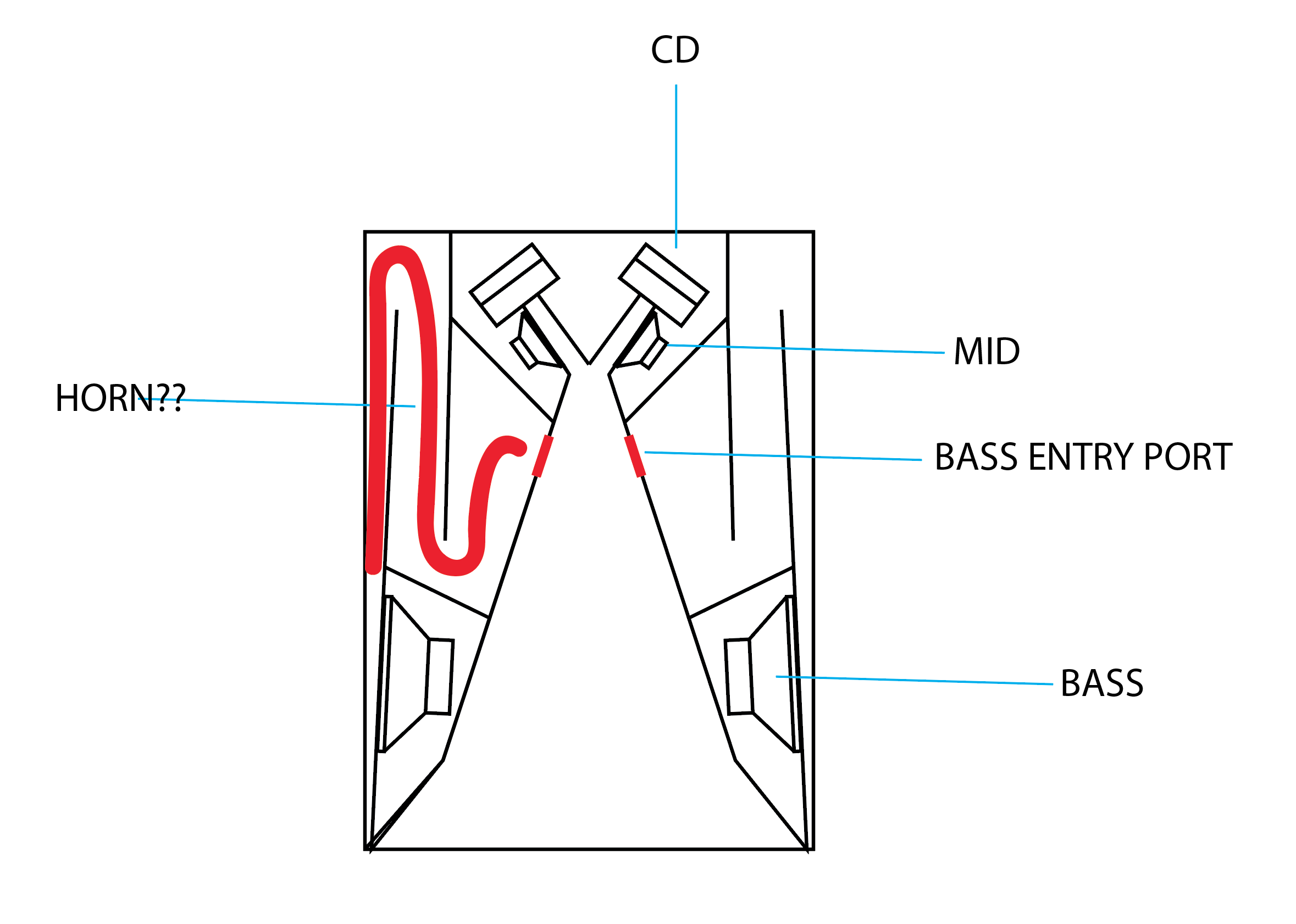
If I were to model the horn in Akabak, it wouldn’t be a horn at the end as large chamber is now huge with a small exit. The boundary condition is the exit aperture. For a horn to be a horn, the exit aperture needs to be expanding and larger than the inlet aperture. The sound waves won’t “know” that it’s a horn and what you are left with is similar to a mass loaded expanding cross section transmission line. The horn expansion is really a waste of wood and complexity for naught.
It's a mass loaded horn.
Same idea as a mass loaded transmission line, but a horn.
There's a lot of good reasons to go this route, here's a few:
In a Jericho horn or a Unity horn, as the size of the box gets smaller and smaller, there's less loading on the midranges and the woofers. This is because they're offset.
For instance, in a Danley SH-50, there are dual twelve inch woofers and they're barely loaded by the horn at all.
If one could horn load the twelves, you could probably get away with something smaller. For instance, a horn loaded 8" or 10" can generally produce about as much output as a 12" in a reflex box.
By going with a mass loaded horn, you can horn load the woofers in a Jericho or Unity horn.
The complexity of the box gets quite gnarly, but thanks to 3D software and CNC robots, it's possible to build it.
There's a handful of additional advantages too:
* the woofers are much better protected from the weather.
* By horn loading the woofers, you can potentially get more output than a vented box. For instance, you could use an eight or a twelve and you could 'push' the F3 of the woofer up higher. This is something that's very difficult to do with a vented box, because with a vented box your response shape is hugely influenced by the QTS of the woofer. With a mass-loaded-front-loaded horn you can juggle the variables and sacrifice low frequency extension for additional output. This is especially useful if your project will include subwoofers, and all of the J7 deployments have included subwoofers. You could argue that the Jericho J7-95 is the most power sub/satellite package the world has ever seen
")
Last edited:
Directly from the patent. Ideally, you'd want the bandpass to be higher in frequency than the crossover, while having the HF rolloff to be lower. The point is that to counteract the time delay given by the path length difference between the HF and the mids, you necessarily need to have at the crossover point 90 degree of phase difference (if they are 1/4 wavelength appart at the crossover frequency). Of course, this does not account for any remaining reactance from the drivers themselves.In your 1st post you said the basic synergy horn uses 1st order xo's. Can I ask where you got that information as I am having trouble understanding due to the bandpass nature of the mids and the natural roll off of the tweeters ?
(Unless you mean 1st order electrical ? )
Thanks,
Rob.
I'm starting to lean towards mark100's opinion in that this part of the patent is a bit of a smokescreen.
The goal is to have linear phase across the whole bandwidth. Pragmatically speaking, you have to account for the remaining reactance of the drivers. Also, you might want to put the first cancellation notch a bit above the crossover point, so there now is less than 90 degree of phase to correct for. Then there is the remaining reactance of the acoustic bandpass filter. You see where this is going... At the end of the day, you'll need to measure the responses of each drivers and tweak the crossover of you want somewhat linear phase. Of this, I'm aware of. And it becomes certainly doable with any orders if you allow for time delays.
My initial point was mostly concerned with attaining somewhat linear phase with only passive crossovers. Danley does it on some model. But in this case think about this: the bandpass, the rolloff and the lowpass in the crossover all delay the phase of the mids output. On the other hand, the LF rolloff and the highpass advance the phase on the highs and the only delay on the phase is given by the path delay, with respect to the mids. By tweaking crossovers, you can arrive at summation at the crossover point. However, it seems almost impossible to escape the phase shift at the crossover. This is because midband, the phase will have a given slope for each drivers, but then a much sharper slope at the crossover point if the acoustic crossover high order.
The only ways out I can see in that situation is to use time delays with DSP, to use first order crossovers with well behaved, wide bandwidth drivers or to have a complicated crossover that mess around with the phase midband, like I suggested earlier (e.g. using delay network, "detuned" crossover filters, etc.)
I think I share some of your issues with the presentation in the patent. However, I fail to see how the phase curve illuminates the issue. I never understood the patent to mean "flat" phase curve. A linear phase accross the bandwidth, no matter how steep, achieves the same as this is just a global time delay.Hi Rob, yeah, I don't know how i let myself go down that first-order rabbit hole....what a crock....all twas needed was a look at the Danley phase traces...(a bit sneaky with the scale imo
What surprises me, though, is how one gets there using steep IIR crossovers. Increasing the order only increases the phase shift for both the mids and the highs (they move in opposite direction). Short of "smearing out" the crossover point by detuning the filters (which would require a big overlap region) or using allpass sections, I do not see how that can be possible.
Indeed! That was the whole point of this thread! However, I now know the price to pay: unless you do some weird shenanigans like I'm trying now, the bandwidth of your woofer is limited to be below the frequency where the length of the mass loaded pre-horn is 1/4 of the wavelength.By going with a mass loaded horn, you can horn load the woofers in a Jericho or Unity horn.
It's a mass loaded horn.
Same idea as a mass loaded transmission line, but a horn.
If the exit terminus is a small hole, it’s no longer a horn but a TL. It’s all “waveguide” elements to Akabak. But in Akabak, a horn radiator is generally open and same size as the expanded final cross sectional area. To model this, you would need to add a short “duct” element to the exit closed off wall.
If you unfolded the “mass loaded horn” it would look like a Voigt pipe MLTL speaker. No one calls that a mass loaded horn. But like I said, it’s all a name.
A horn is also characterized by wide bandwidth. Whereas the constricted mass loaded TL is of very limited bandwidth. The gain you get is purely volume based. I think if you made a rectangular box the same volume with the same size exit hole - it would behave very similarly.
Exactly, and this is how I simulate it, not with Akabak, but with my own code (it's all the same equations at the end of the day).It’s all “waveguide” elements to Akabak. But in Akabak, a horn radiator is generally open and same size as the expanded final cross sectional area. To model this, you would need to add a short “duct” element to the exit closed off wall.
I agree, but I, for one, thought it was just another name for the same thing.If you unfolded the “mass loaded horn” it would look like a Voigt pipe MLTL speaker. No one calls that a mass loaded horn. But like I said, it’s all a name.
Well, in a way, yes, but it ain't black and white. In the limit of the port length being infinitesimal, it will not impact the response at all, so, there has to be a transition. Also, this is all to be viewed with respect to the wavelength of interest. At sufficiently low frequencies, the discontinuity of the port won't matter anymore.A horn is also characterized by wide bandwidth. Whereas the constricted mass loaded TL is of very limited bandwidth.
Hmm, not sure I agree here. There is the Helmholtz resonance, and then there is the pipe resonance. Of course under the proper limits, "everything looks alike". Loading a pipe (or expanding profile, for that matter) with a port only changes the boundary conditions. Instead of having a displacement maxima for an open end or a minima for a closed end, a port yields an in between boundary conditions.The gain you get is purely volume based. I think if you made a rectangular box the same volume with the same size exit hole - it would behave very similarly.
In fact, this is what I'm trying to exploit: an in between where you damp the resonance and add compliance at the end to smoothen the transition at the first pipe resonance. This first pipe resonance was my main problem as it fell in required bandwidth. Using ports was not directly related to increasing bass output, but rather to prevent impacting HF response and polars. The question was how to physically couple a horn to another horn segment using a physically small aperture (smaller than the mouth of the first segment) all in the goal of increasing driver loading wide band. I point this out a bit earlier in the thread.
Regards,
Geoffroy
I think I share some of your issues with the presentation in the patent. However, I fail to see how the phase curve illuminates the issue. I never understood the patent to mean "flat" phase curve. A linear phase accross the bandwidth, no matter how steep, achieves the same as this is just a global time delay.
What surprises me, though, is how one gets there using steep IIR crossovers. Increasing the order only increases the phase shift for both the mids and the highs (they move in opposite direction). Short of "smearing out" the crossover point by detuning the filters (which would require a big overlap region) or using allpass sections, I do not see how that can be possible.
Hi Fers,
Just to make sure we are on the same page with terminology, pls bear with me laying out my understanding of what linear phase means..
Which is, that linear phase will plot as a straight line against frequency, when the frequency scale is linear.
If this condition is met, then the removal of the global time delay implicit in the slope of the straight line, will flatten the line to lay horizontal at zero degrees. True linear "flat" phase.
I think this is what you were saying too, re global delay?
When the frequency scale is logarithmic, a true linear phase trace will also be a flat line at zero, when the global time delay is removed.
However, if the global time delay is not removed, the phase will be curved, not a sloping straight line as with the linear freq scale.
So the point of all the above is to say, linear phase does in fact mean "flat phase" after global delay is removed on either scale.
But a sloped straight line on a log scale has phase rotation.
Whereas on a linear scale a sloped straight line does not have phase rotation.
And since virtually every phase trace we ever see is on a log scale with global delay removed,... unless it is flat at zero degrees, it is not linear phase.
Even if it has a straight sloping line, it shows phase rotation.....rotation that no adjustment to global delay can remove.
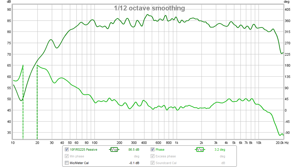
When I look at the SH50 phase trace, from say 80Hz to 13kHz, it shows about 450 degrees of rotation. Since there are two xovers in play, i guesstimate the rotation to split to about 225 degrees each, or about 2.5 orders each.
Damn nice work ! But certainly not acoustic first order.
(i never thought the patent was meaning flat phase either)
The thing is, you simply cannot avoid phase rotation with IIR crossovers. IIR xovers all induce phase rotation, even first order, huh?
Like you see is impossible, steep IIR simply xovers can't be used to achieve lower order acoustic results.
Some folks say allpass filters can get you there. And i agree a little, but only when starting with very low order xovers, and a low number of sections like a 2-way. Higher order and more sections quickly make allpass phase adjustment a theoretical pipedream imo.
mark,
Yes you are right, I overlooked the log axis when looking at the phase in the graph... Sorry for the confusion.
It seems that the patent suggesting low order crossovers, specifically first order electrical, so that the resulting phase shift is countered by the path difference, is a bit of a red herring. Thus, it seems the real point being made here is that one needs to take into account this path difference when doing the crossover to maintain summation. Approaching it this way would simplify my build!
Speaking of which, irrespective of linear phase or not, I see as one of the great advantages of the unity designs that the crossover designed is simplified as one only have to consider summation at one point in the horn where all the drivers contribute a fixed phase, by design. If done well, there should be no issues of lobing, tilting, etc. Then, in an ideal world, the summed response is smoothly distributed in the coverage angle due to the constant directivity. In a way, the problem becomes unidimensional.
This brings another question. In that case, it seems one should aim for a flat power response crossover, instead of a flat summation on the design axis. If the constant directivity is fulfilled, then one would get automatically a flat response. If that is the case, then the crossover designs that relies on the side nulls to get flat response on axis (such as LR) are not the best starting point. I guess one still has a better loading with the increase in radiating area at the crossover point. However, the drivers are already fully loaded by the horn at that point, so I don't expect a significant additional gain in the radiating efficiency.
Regards,
Geoffroy
The thing is, you simply cannot avoid phase rotation with IIR crossovers. IIR xovers all induce phase rotation, even first order, huh?
Like you see is impossible, steep IIR simply xovers can't be used to achieve lower order acoustic results.
The Harsch XO is all IIR and uses 4th order and 2nd order to achieve relatively flat phase (no wraps) and 55 deg bump.
S. Harsch XO
I managed to implement it passively even (pure luck with the drivers):Simple Passive Harsch XO Using PTT6.5 and RS28F in a Waveguide
But can be very effective when done via DSP with IIR filters.
First order XO’s done right don’t induce phase rotation:
10F/8424 & RS225-8 FAST / WAW Ref Monitor
I showed this with both DSP IIR and passive XO. Here is measured response and phase - XO is at 900Hz
Last edited:
Yep, Harsch is pretty cool. I like that it provides a 4th order low-pass, and that phase stays relatively flat. Also like the work you did for taking it to a 3-way.
I know electrical first order HP and LP sum to flat phase, despite each individually having some phase rotation. I keep meaning to look into that, how the individual rotation disappears. (i just have a hard time getting interested in IIR lol )
And I've seen that 3-ways using first orders can also stay flat if you spread the xover points away from each other. That is, spread apart the xover freq for the low LP and the mid HP, ....and same for mid LP and high HP.
I totally get using low order with well behaved drivers, especially if they also have tight geometric spacing.
With the right port sizes and placements, i can see low order working super with synergies.
Personally, i just think the low order route is too much hard work for results that don't end up being quite as good, as from an easier route using steep linear phase xovers. (For me steep begins at 8th order)
8th order is a brick wall?
No, of course not. Not sure how brick wall has entered into the discussion?
I use lin phase LR's up to 16th order. No brick wall use to date, although I could see it for HF to VHF handoffs.
xrk971, that's very good! I don't even see any 55 degree bump around 900Hz. The extension you made for the 3 way makes me think of the phase link concept, but extended for 4th order BW. The phase link becomes the bessel 2nd order bandpass. I haven't checked that the transfer function actually is unity, though, but is seems similar.
It's kind of the point, hehe... I want to see how good I can make the enclosure with a passive XO between mids/highs. I'm making my life hard using drivers chosen for prices and non-standard design (the subject of this thread).Personally, i just think the low order route is too much hard work for results that don't end up being quite as good, as from an easier route using steep linear phase xovers. (For me steep begins at 8th order)
Of course the speakon jack always has 4 poles if I get tired...
In any case, when the prototype is built, I will use my miniDSP before finalizing the passive XO.xrk971, that's very good! I don't even see any 55 degree bump around 900Hz. The extension you made for the 3 way makes me think of the phase link concept, but extended for 4th order BW. The phase link becomes the bessel 2nd order bandpass. I haven't checked that the transfer function actually is unity, though, but is seems similar.
That plot was the 1st order passive XO.
Here is the 55deg bump above the 3.5kHz crossover in the PTT6.5 and RS28F in waveguide:
mark,
Speaking of which, irrespective of linear phase or not, I see as one of the great advantages of the unity designs that the crossover designed is simplified as one only have to consider summation at one point in the horn where all the drivers contribute a fixed phase, by design. If done well, there should be no issues of lobing, tilting, etc. Then, in an ideal world, the summed response is smoothly distributed in the coverage angle due to the constant directivity. In a way, the problem becomes unidimensional.
This brings another question. In that case, it seems one should aim for a flat power response crossover, instead of a flat summation on the design axis. If the constant directivity is fulfilled, then one would get automatically a flat response. If that is the case, then the crossover designs that relies on the side nulls to get flat response on axis (such as LR) are not the best starting point. I guess one still has a better loading with the increase in radiating area at the crossover point. However, the drivers are already fully loaded by the horn at that point, so I don't expect a significant additional gain in the radiating efficiency.
Regards,
Geoffroy
I don't think i'm fully getting what your saying here.. with regards to a synergy that is.
My thinking is that the on-and-off axis response, the pattern, will be more governed by the synergy horn size and wall angles, secondary flare, etc.
And not so much effected by x-over order and how it might change particular loadings away from xover freq.
Interesting idea that loading might be effected....I guess it has to, to some degree? thx !
It's kind of the point, hehe... I want to see how good I can make the enclosure with a passive XO between mids/highs. I'm making my life hard using drivers chosen for prices and non-standard design (the subject of this thread).
Of course the speakon jack always has 4 poles if I get tired...
Yes my bad, my friend
Lord knows it's all about what we want and having fun
My latest syn7 uses NL8's lol
Well I've just read the patent( for about the 10th time ) and I still couldn't find any reference to 1st order slopes.
I found references to non integer slopes and roll offs that were 'non constant' slopes.
I'm still running round in circles here
Cheers,
Rob.
I found references to non integer slopes and roll offs that were 'non constant' slopes.
I'm still running round in circles here
Cheers,
Rob.
Attachments
Oops. Still quite good!That plot was the 1st order passive XO.
- Status
- This old topic is closed. If you want to reopen this topic, contact a moderator using the "Report Post" button.
- Home
- Loudspeakers
- Multi-Way
- Increasing loading of midbass in synergy horn