By adding this oval ring, and gluing the spider completely to it,
The only challenge I'd have would be to ensure sufficient glue area and strength, and enough overlap past the ring to ensure that it doesn't rub, but this is certainly an interesting idea.
I believe it will end up around 5-600 USD/pc, and it is hard to get a classic TAD, Coral, Altec, Fostex etc. for that kind of money these days.
Not sure if you just building 1 pair or tooling up and buying parts in 20's which is the minimum for OEM prices, but please research the massively important but rarely discussed " Voice coil induced Thermal Distortion"
See the attached PDF by the genius Michael Gerstgrasser and his website here: Audio and Loudspeaker Design Guide Lines
PS, The attached Beyma 15 inch sounds superb crossed over at 800Hz to a broad band / full range driver, never tried a CD / horn but would be even better I guess. With Eq its flat to 30Hz at 105dB continuous (AES) SPL.
Attachments
The only challenge I'd have would be to ensure sufficient glue area and strength, and enough overlap past the ring to ensure that it doesn't rub, but this is certainly an interesting idea.
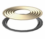
I have been thinking about this, and I think the solution is pretty safe:
As you can see, the shape of the ring (where it is in contact with the spider) has the exact same shape as the spider. The spider should, off course, be fully glued to the ring. Any missing glue could quickly turn into some noise.
Attachments
See the attached PDF by the genius Michael Gerstgrasser and his website here: Audio and Loudspeaker Design Guide Lines
PS, The attached Beyma 15 inch sounds superb crossed over at 800Hz to a broad band / full range driver, never tried a CD / horn but would be even better I guess. With Eq its flat to 30Hz at 105dB continuous (AES) SPL.
I am afraid this distortion document has some serious errors.
First of all, the way heat behaves in speakers. You do not have 115dB contineously in a speaker like this. It is, off course, possible, but 115dB on average is extremely loud. Even peaking at 120dB you rarely experience as much as 111dB contineous power over a 10 second period. That is 1/8 of the power, so if you have 115dB transients (which is how I read the document) you have just over 1W.
Secondly, assuming the cooling factor of the coil is far above 100K/W really does not make sense, not even for a tweeter. In the example shown in the link, he uses a 1 inch dome tweeter. My driver has 120 times the surface area and 4 times the efficiency as that tweeter.
But the really bad part of the document is how he handle numbers. First off all, if you increase the Re from 5,5 to 7,5 ohm, it does not add distortion. The parameters change, but it does not add any kind of distortion by itself. The change in T/S-parameters is real, but that is not a source of distortion by itself. As far as I can see, he assumes that the coil changes its temperature for every signal period (in his 10kHz example that means cooling from 120degrees to 20 degrees, and heating up again, 20 000 times every second). That would lead to a heavily modulated sound due to the rapid changes in T/S parameters, but we all understand that it is not going to happen anywhere near as fast as this.
The reduction in sensitivity, resulting from the reduction in current, is also real, but even with a 35% reduction in the current, the difference in output power equals a reduction in the pass band of about 2dB. This is not happening in every signal period, but even if it did it would still be less than 1% harmonic distortion.
So, as you understand, I have taken care of heat in this motor, but the reason why I have done that is not because it causes harmonic distortion, but because it changes the way the drivers sensitivity (relative to other drivers in the same system) and because it changes the relationship between the resonant response and the pass band (AKA T/S-parameters).
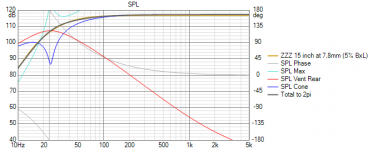
Even running really hard, It is highly unlikely that you will ever see more than 20 degrees increase in temperature. This is probably not going to translate into measurable distortion. The change in T/S parameters will be minor, and the change in both temperature, BL(x), Le(x) and suspension has been extremely precisely simulated, and it leads to the change you can see here:
As you can see, the change of intensity in the pass band is extremely small, and this is at a dynamic 150W input power, delivering 123dB for two drivers, one in each stereo speaker. The change in the resonant part (low frequency roll off) is also minor.
Remember that this not only includes voice coil heating, but also all other changes that would occur. This is a kind of a "worst case scenario".
Attachments
Not sure if you just building 1 pair or tooling up and buying parts in 20's which is the minimum for OEM prices
The interest is really strong, and I have also been contacted by a loudspeaker manufacturer, so I most likely have to make at least 100 pcs. This is also why I have suggested s price.
@ICG:
I believe all of the issues you mention in your post are well covered by previous answers. For the purpose of the thread, I see no point in discussing those details further.
Actually, the issues are indeed not be covered at all. Intermodulation distortion is a HUGE issue and not adressed properly before. You've mentioned it but actually did not answer to oks81's argument nor mine. Since intermodulation isn't a harmonic distortion, it's VASTLY undervaluated by you. The problem is, since it's not a harmonic and even less a linear distortion, it is an issue you haven't adressed AT ALL and will have a huge influence on the sound reproduction in the midrange.
Aside from that, you did not have taken into account that any impedance control (pole plate copper cover or aluminium pole plate ring) will impact your magnetic flux, because it increases your effective air gap - the aluminium or copper ring does not 'count' towards the magnetic structure. And since you've planning on a double coil drive with two gaps, your calculation is off by at least factor 4, but since your 'brilliant' impedance compenstaion construction by most likely by 8 to 20x. Which means, you'll have to increase your magnetic motor by approximately that factor. That is the exact reason why double coil drivers are actually NOT used in the midrange.
First, as phase_accurate says, it doesn`t mather if the coils are in parallell or in series.
Well, mo matter if he says that, physics say otherwise. It's an actually very easy equation, since amplifiers are - in general - voltage sources, just apply Ohm's law to the appropirate impedance (added, since serial) curve and you will undoubtetly notice, it actually reduces the power (and therefore, the spl) by a huge ammount.
Second, the doppler effect. If this is an big issue, how about 6,5" and 8" thats more normally used in hifi speakers? Their freq range often about 30-2khz?
It's not (only) about the Doppler effect. It's about the intermodulation distortion! Yes, a 15" driver will have lower intermodulation distortion than a 6" or 8". But that's ONLY if it does a lower excursion. That means, if the 15" does the same excursion in the midrange like a 6" or a 8", it will have the same intermodulation distortion. And yes, that includes the lower beamwidth of the 15" already.
I don`t say it is an easy job for an 15" to play up to 1khz.
But you have to look at the real issues. Cone break up. Intermodulation in motor. Suspension. How much mms do it need, preferably light for the upper range.
YES! Exactly that! With that much of an excursion, the intermodulation will NOT allow a precise midrange signal reproduction! Excursion is the key since the intermodulation distortion is directly dependent on it! That means, a midrange capable driver cannot exceed a certain excursion since it would introduce a huge distortion! Look at midrange-able drivers of P-Audio, RCF or whatever brand you'd like, you'll find that (after calculating ((winding height-pole plate height)/2) the max linear excursion of midrange-able15" drivers are ~3,5mm. Give or take some for the drivers manufacturers cacluclation, but you'll find there are none of high excursion drivers among them. The reason is easy to determine, above that excursion the distortion gets too high to reproduce any reasonable midrange.
On the other hand there has been build 15" for long time that do this job quite good.
TAD 2402 monitor. JBL Everest series. JBL K2. JBL M2 and so on.
In the K2 the 15" is crossed at 900hz. I don`t see much complaints about these kind of speakers all having 15" crossed in the 7-900hz region.
YES! But none of it do an excursion of 12mm! Actually, you'll find, they'll do no more than 3-4mm!
Well, mo matter if he says that, physics say otherwise.
I and the physics still say that. You should not take things out of context. The discussion back then was about the upper corner frequency caused by Lvc and Re.
That is the exact reason why double coil drivers are actually NOT used in the midrange.
There are enough exaples to prove the contrary. For instance all those Studio and PA Woofers for two way systems by JBL.
Eighteensound for instance has two new tetracoil models aimed at two way applications. An interesting statment from them is:
"Dual gap motors linearize inductance and the perfect balance we reached between the motor and the ultra linear suspension allows both very high excursion and extreme precision in the mid band with the lowest intermodulation distortion in the professional market."
I also think that you completely misunderstood the intention behind that design. It is meant to lower nonlinear distortion by needing less excursion than a smaller driver for a given SPL and not for being used to reach disco levels. Personally I could do with 5mm of x-max. Which would also be sufficient for most users. His intention is to have a driver that still has some marging left when excurions in the 5 mm or whatever order are reached. How much benefit this will have I don't know.
But there is definitley a lack of affordable 15" studio woofers at the moment. But there are some Faital and Beyma Drivers (and others of Course) that are already close to studio woofers and which would probably only need minor changes in order to be considered as one. I guess one would also have to order 100 pieces or more to have them customise one of their existing models.
Regards
Charles
1: I answered about VC serial/parallel in the matter of t/s, not the amp that is connected Yes I know ohms law.
2: I answered to the doppler effect, not intermodulation.
3: The intermodulation in the driver I will leave to Snickers to explain and what he has done in the motor to lower this. Keywords: Saturated VC gap, high flux, single layer VC.
4: Yes I know how to calculate Xmax. Yes I know much of the existing drivers have short Xmax. This driver have 12mm Xmax because it can, and not because it`s nessesary to use it to Xmax.
5: Several drivers have dual VC and works fine in midrange.
Try at least to listen to the moo and understand it, not moo against it.
ICG is correct about intermodulation due to excursion. ( as an aside to driver non-linear motor / suspension behavior )
AES Convention Paper 7840 ( listed as 15035 ) investigates this phenomenon, titled "Modeling the Intermodulation Distortion of a Coaxial Loudspeaker"
AES E-Library >> Modeling the Intermodulation Distortion of a Coaxial Loudspeaker
The same phenomenon applies to a wide band drive unit undergoing a large excursion with simultaneous low frequencies and high frequencies being reproduced.
I haven't been on here for a very long time and I'm sorry to not follow up.
@diyuser2010: Your mentioning and linking pages are exactly what I wanted to mention/emphase.
Besides the excursion and intermodulation distortion, the high impedance poses an extreme problem regarding the amplifier. With an impedance (or for simplier estimate: Re) of 32 Ohm and a target max spl of ~105 dB (which isn't very high for a 15" driver) you need a very high rail voltage of about ~70V. That means, you'd have to use a high power PA amplifier (>1600W@4Ohm). Such amps got usually disadvantages in HIFI use are frowned upon, like fan noise, idle noise floor etc.
I've got the distinctive impression you've only chose the very high impedance of ~32 Ohm because of the 'impressive' high BL you'd get from it. Since the BL is directly dependent on the impedance, your goal to get impressive numbers won't hold a real world check and your proposed driver would only fit a theoretical scenario (let alone the performance on a very highly impedance dependent tube amp or class D amp) and a high excursion leading to very high distortion, it seems a different approach would be more appropriate.
To be constructive: My suggestion would be to keep the maximum excursion much lower and keep the cone all the time in a linear/constant magnet field. That can be achieved by a broader magnet gap depth and an underhung VC. Since you can't use a high excursion while reproducing midrange sounds, that seems to be a much more preferable path to follow.
ICG is correct about intermodulation due to excursion. ( as an aside to driver non-linear motor / suspension behavior )
AES Convention Paper 7840 ( listed as 15035 ) investigates this phenomenon, titled "Modeling the Intermodulation Distortion of a Coaxial Loudspeaker"
AES E-Library >> Modeling the Intermodulation Distortion of a Coaxial Loudspeaker
The same phenomenon applies to a wide band drive unit undergoing a large excursion with simultaneous low frequencies and high frequencies being reproduced.
This is actually not relevant as this paper is about how the sound is modulated by the waveguide changing shape while the driver is stationary. This is a well known and significantly more audible effect than the fundamental intermodulation distortion caused by a cone reproducing several different signals at the same time.
Intermodulation in driver cones is a well documented and quite easily understood parameter. It is not very frequency dependent, it is actually only improved marginally by reducing the bandwidth of the driver, and it is very dependent on driver size and SPL.
If you use a driver down to 20Hz and take advantage of a 4mm excursion, you will not have a lot of modulation. If you take advantage of the same excursion down to 60Hz, you will have a far more audible effect. This is because we increase the SPL by 11dB. But if this same driver adds another octave at the same level, the intermodulation distortion caused by doppler is only increased marginally.
So if we replace the 15 inch driver in the midrange by lets say a 6,5 inch midrange and cross them over at say 100Hz, the case of doppler will be far worse, but it is not for frequencies reproduced by the midrange driver.
For a coaxial driver the situation is very different. The intermodulation is not doppler alone, and the doppler effect is a quite small part of the total intermodulation distortion. By removing the low frequency part of the signal here, we do not improve very much on the doppler part, but we do improve significantly on the effects of shape changing, so unlike the bass/midrange-example we will have a huge benefit of adding a woofer to that system.
@diyuser2010: Your mentioning and linking pages are exactly what I wanted to mention/emphase.
You should take some time reading what that is actually about.
Besides the excursion and intermodulation distortion, the high impedance poses an extreme problem regarding the amplifier. With an impedance (or for simplier estimate: Re) of 32 Ohm and a target max spl of ~105 dB (which isn't very high for a 15" driver) you need a very high rail voltage of about ~70V. That means, you'd have to use a high power PA amplifier (>1600W@4Ohm). Such amps got usually disadvantages in HIFI use are frowned upon, like fan noise, idle noise floor etc.
And if you spent some time reading, you would notice that this is a dual coil woofer, and the "standard connection" would be using the two coils in parallell, adding up to 8 ohms nominal.
Using the coils in series will be beneficial for large line arrays where there is an advantage of using the woofers in parallell. Especially for slot loading with dual oposing woofers, connecting them in series might cause a very nasty effect as they are running as a divider both mechanically and electrically.
Rail voltages of near 100V is available in Ncore-amplifiers. In reality we can get about 21dB up using such an amp, and with an efficiency of 95dB we can reach 116dB for each driver. Such an amp easily runs 8-12 drivers at the same time, leading to a headroom of 134-140dB on each side, still at low distortion.
I've got the distinctive impression you've only chose the very high impedance of ~32 Ohm because of the 'impressive' high BL you'd get from it. Since the BL is directly dependent on the impedance, your goal to get impressive numbers won't hold a real world check and your proposed driver would only fit a theoretical scenario (let alone the performance on a very highly impedance dependent tube amp or class D amp) and a high excursion leading to very high distortion, it seems a different approach would be more appropriate.
The force factor should be correct. Not "as high as possible" or anything else. It is a currenct weighted parameter, so it is a 1/sqrt2 dependendt on the resistance of the coil, so therefore, if you double the Re, the force factor will for example increase from 20 to 28,2. That is neither impressive or unimpressive.
To be constructive: My suggestion would be to keep the maximum excursion much lower and keep the cone all the time in a linear/constant magnet field. That can be achieved by a broader magnet gap depth and an underhung VC. Since you can't use a high excursion while reproducing midrange sounds, that seems to be a much more preferable path to follow.
Reducing the maximum excursion will reduce the available headroom, and increase distortion at all levels. I understand it is important for you to be right, but for me that is actually not very important.
Your suggestion of changing it to an under hung driver is a very poor one. It will reduce the power handling, it will require far more magnet mass, it will make the distortion go up, and give a significant increase in field modulation.
You might be surprised by this, but you can actually run any driver at short excursion. This driver is designed to perform as good as possible, also at short excursions. The motor was slightly modified a few months ago, and bot the BL(x) and BL(i) is as good as it can possibly be at shorter excursions. At 110dB the BL is off by 0,088% (no that was not mistyped), and, running at 32 ohms, at 10 amps, the force factor is only off by 0,11% (that equals around 1500W). You would not get anywhere near that with an under hung motor. And you will not improve performance by reducing the available headroom.
So, while the first samples are finally being built, I would like to clearify for those who might still be confused about doppler and IMD:
Doppler distortion vs IMD? - PURIFI
Doppler distortion vs IMD? - PURIFI
We used a version of the motor that we have developed for an OEM customer. I think it would be up to them if they want to disclose the Klippel curves later on. But to give you an idea, it is quite similar to the JBL 1501-AL1. At this point, a bit of work is remaining on the suspension (we got some pre tension due to assembly offset) and it seems like we should add another shorting ring. However, since the magnet rings were lacking some punch, the motor is not as saturated as it would normally be, so it remains to see what the correct rings will change.
I see. Will this remain the situation, or will you be able to share Klippel data from the coming/final iterations. If it’s close to the 1501-Al, that is very good already, and the HF looks much more extended and well behaved than the 1501.
Will be exciting to follow this project, and perhaps buying some drivers one day.
Will be exciting to follow this project, and perhaps buying some drivers one day.
- Home
- Loudspeakers
- Multi-Way
- The birth of a 15 inch woofer