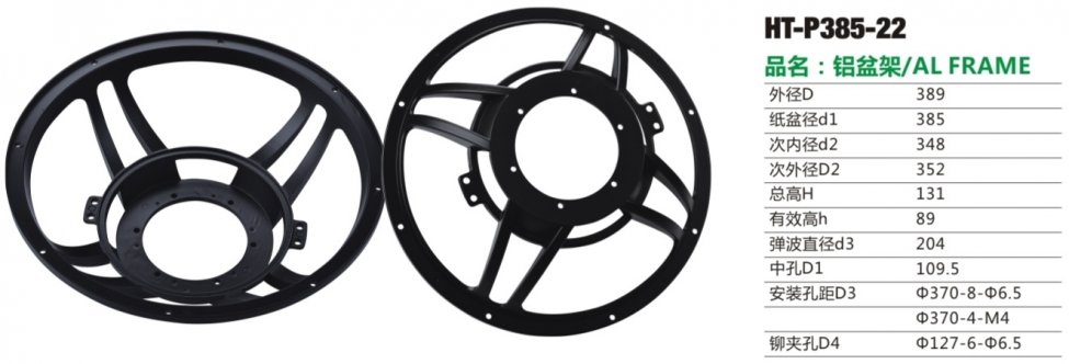
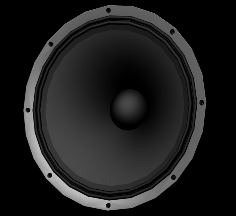
So the frame I went for is not the kind you would think of for a "5000W car audio competition subwoofer", but rather a transparent one that is far more sturdy than we would ever need, and in addition has some decent openings for air to escape from under the spider. It also has the necessary depth I need from surround landing to spider landing for a 15 inch cone with 3 inch voice coil (which naturally has a deeper profile than what it would with a 4 inch coil), good height from spider landing to motor mount to allow some serious excursion before something is damaged, and last but not least, a spider landing of respectable 204mm to allow for a more linear suspension.
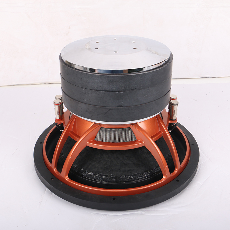

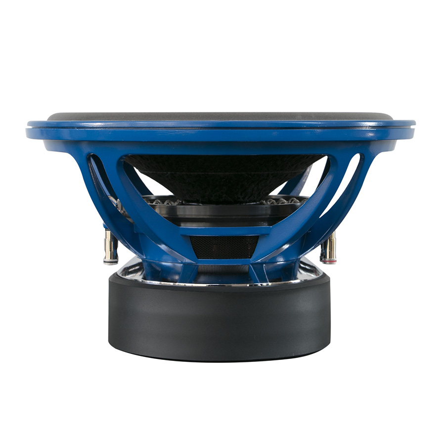
This frame comes with two terminals positioned on each side, so balanced lead out wires is possible. By default it does not have any gasket or trim ring, so to make it look a bit better I plan to finish it off with a ring that looks something like this:

This frame comes with two terminals positioned on each side, so balanced lead out wires is possible. By default it does not have any gasket or trim ring, so to make it look a bit better I plan to finish it off with a ring that looks something like this:
I am not familiar with that Beyma driver, but in what way would you regard it to have more desirable parameters?
Nothing special really. 15K200 has a little higher Qms, larger voice coil and is a bit more sensitive W/m.
Last edited:
I checked the datasheet now. It has a stiffer suspension and a fair bit more force factor than my target parameters. It would roll off a bit early in the same box.Nothing special really. 15K200 has a little higher Qms, larger voice coil and is a bit more sensitive W/m.
The coil is larger, but it has only one. In terms of cone coupling it is definitely larger, but in terms of heat it would be more relevant to say it is 2 inches smaller.
The qms is one of the hardest parameters to predict. But with relatively low loss suspension, non conductive bobbin and low air resistance it will for sure be high.
Of course. Double coil, that JBL uses for quite some time, will make the heat problem less of a problem. On the other hand, if one warms up a coil in a woofer of that sensitivity and size enough to change ts parameters, he really needs a PA loudspeakers - and more than two, in my opinion.
Either way, you are doing things as you see fit and i am subscribed to this thread. I'd really like to see this project successfully finished.
Either way, you are doing things as you see fit and i am subscribed to this thread. I'd really like to see this project successfully finished.
Of course. Double coil, that JBL uses for quite some time, will make the heat problem less of a problem. On the other hand, if one warms up a coil in a woofer of that sensitivity and size enough to change ts parameters, he really needs a PA loudspeakers - and more than two, in my opinion.
I think your opinion is spot on. I did not choose double coil/double gap to cope with heat, but to make it symmetrical so that I could focus more on DC components (Not the kind of DC-components associated with traditional motors, but force factor not being the the same independent of polarity).
There are some rare occations where the coils is very short, and air is not moving very much through the gap. We often focus on the coil diameter, but doubling the diameter really does not do much more to cope with heating than doubling the length of the coil. Anyway, what I meant to say is that the sensitivity does not necessarily solve this, even with a 4 inch coil, if the coil is very short.
The surface area of this coil is around 160sqcm. The Beyma 15k200 has 66sqcm. The crazy BMS 18N862 actually has 160sqcm voice coil surface, and it has 267g Mms to drag around. That one probably has some degree of forced air cooling, but it is rated at 1500W AES noise. My driver will have lower class wire to get less gap between the windings (thinner insulation), and therefore not be able to handle the same amount of heat. But using 1000W AES to simulate heating properties is probably not that far from the truth.
Either way, you are doing things as you see fit and i am subscribed to this thread. I'd really like to see this project successfully finished.
Thanks Zvu! I will post much more tech stuff here, but opinions and discussion are welcome! That kind of discussion is a significant source of knowledge.
There are typically 4 different factors that induces distortion in a motor. All of them does it by changing the relative force factor. They are as follows:
BL(x) - Force factor as function of coil position
BL(i) - Force factor as function of coil current, typically flux modulation
Le(x) - Inductance as function of coil position
Re(T) - DC resistance as function of voice coil temperature
Re(T) is not really a direct source of distortion as it is the change in Re that causes some change in the parameters, and increased Re does not by itself cause distortion if it remains constant. It does, however, impact other parameters that causes harmonic distortion.
BL(x), also known as the large signal force factor, is often described as the main source of harmonic distortion at low frequencies. Strangely, it is not often described as a source of intermodulation distortion, but that is a far bigger problem in real life. Industry standards commonly used to describe X-max are -30% for subwoofers, and -18% for midwoofers. In the pro audio industry they often accept even more loss in force factor than that.
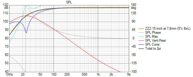
This is what the BL(x) (simulated) looks like for this woofer:
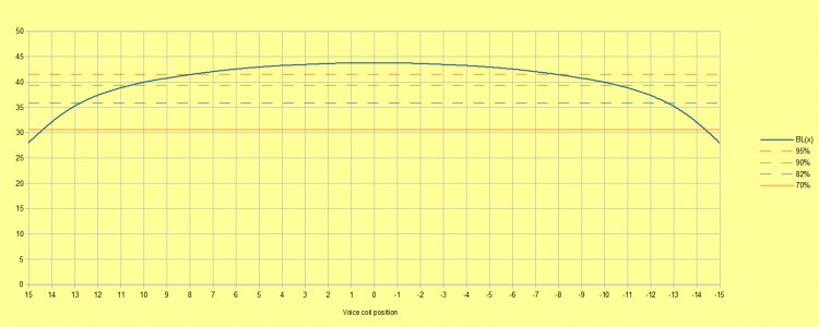
And this is a simulation showing the response as a function of change in force factor from 0 to 8mm:
BL(x) - Force factor as function of coil position
BL(i) - Force factor as function of coil current, typically flux modulation
Le(x) - Inductance as function of coil position
Re(T) - DC resistance as function of voice coil temperature
Re(T) is not really a direct source of distortion as it is the change in Re that causes some change in the parameters, and increased Re does not by itself cause distortion if it remains constant. It does, however, impact other parameters that causes harmonic distortion.
BL(x), also known as the large signal force factor, is often described as the main source of harmonic distortion at low frequencies. Strangely, it is not often described as a source of intermodulation distortion, but that is a far bigger problem in real life. Industry standards commonly used to describe X-max are -30% for subwoofers, and -18% for midwoofers. In the pro audio industry they often accept even more loss in force factor than that.
This is what the BL(x) (simulated) looks like for this woofer:
And this is a simulation showing the response as a function of change in force factor from 0 to 8mm:
Jumping resonance treshold and suspension:
A less known non linearity effect in speaker drivers is is jumping resonance as a result of suspension stiffness increasing with amplitude.
The effect is described in this Wikipedia article:
Nonlinear resonance - Wikipedia
A good illustration of this is the foldover effect. It looks like this:

The curve shows the systems tendency to be resonant. There are several things happening here. First off all, we can see that the width of the treshold decreases with amplitude. This means the system has an increasing Q with amplitude. If we make two identical drivers, except for the suspension being less compliant on one than the other, the one with the highest Fs will also have the highest Q. This is what we clearly see in this diagram.
Secondary, if wee look at the top of the curve, we can see that it ends around +500Hz. So at 300Hz, we can get a skipping effect. As the amplitude goes above ~7 the unit leaves the resonant part. This means the efficiency of the system will be slightly reduced compared to below the treshold. At an amplitude around 30, the system has an efficiency that is lower than at an amplitude of 40. The system amplitude might actually be both 30 and 40 at the same input signal.
So imagine the input signal being dynamic, varying from 0 to 40, the efficiency will vary through the period, jumping in a non linear matter. This leads to higher frequency components being added to the response.
In a real life speaker driver, the resonance shift will not be several octaves. The amount of shift will depend on how progressive the suspension is. An other interesting fact is where in the drivers working range the resonance can be found. Moving Fs in the low end of the working range will both increase amplitude around Fs, but also reduces the frequency and therefore the audibility of the harmonic components. One idea could be to reduce Fs to an octave below the low end (Fb) of the system, but it could also mean a system with reduced stability that copes less well with DC components. Moving Fs up an octave or two will increase distortion audibility, and it will add resonant behavior around 50-120Hz, leading to a less desirable impulse response. In addition to that, resonant behavior also affects higher frequencies and adds intermodulation distortion.
There are basically two different sources of capacitive effect in the simplified speaker model. One is the suspension, the other one is the internal box volume. We can not do much with the box, other than to decide its size. I could, off course set the box volume to 10 000 liters, but it wold not be a practical solution. Many people would probably say the selected 150 liters is too big as well, but that is the chosen compromise.
Then we should turn our focus to the suspension itself, and here we have some choices to make, two of them being especially important for the effect of jumping resonances:
1: The compliance of the suspension decides the drivers Fs. It also decides how well the driver controls DC components in the driver. By selecting a motor geometry that removes DC components we are left with a more free choice of Fs. We could lower it to an extremely low number, but it could create some issues with the midbass, as well as making the driver vulnerable to transients. A well balanced response is what we get when Fs is placed around 20-25Hz. However, the combined resonance is 48Hz, so the box dominates the capacitive components. So at low excursion, the suspension contributes very little to the total resonance.
2: The progressiveness of the suspension is another factor. If the suspension is very progressive, it will quickly become the dominant capacitive factor. Achieving a constant compliance over a large excursion range is therefore a crucial goal. The easiest way to achieve this is to use suspension with fairly long excursion capacity. The spider has a large outer diameter of 8 inches, and, off course, a 3 inch inner diameter. The distance from the bobbin to the edge of the suspension area on the spider is 60mm. The surround is not that wide. It has around 35mm between inner and outer fixed points, which is not bad either, but far from the 60mm of the spider. If the surround is stiffer than the spider, it will become the dominant capacitive component of the suspension. But since it is not as wide as the spider, it will also typically be more progressive. Therefore, the spider should be the stiffer suspension component, while the surround should be the softer one.
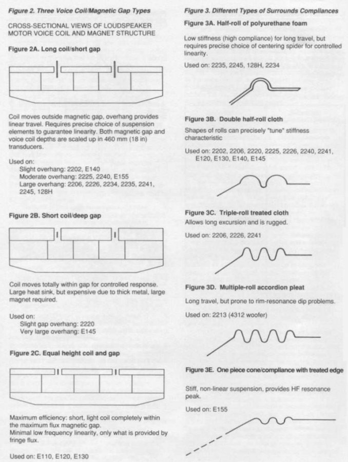
There are also many different profiles to choose from on surrounds. The so called "Double half roll" type is one of the more suitable variant for drivers that are intended to deliver both bass and midrange performance. This is the one selected so far, but I am awaiting some adjustments on this. JBL has also made some pointers on this issue. You can read about them in the right column here:
A less known non linearity effect in speaker drivers is is jumping resonance as a result of suspension stiffness increasing with amplitude.
The effect is described in this Wikipedia article:
Nonlinear resonance - Wikipedia
A good illustration of this is the foldover effect. It looks like this:
The curve shows the systems tendency to be resonant. There are several things happening here. First off all, we can see that the width of the treshold decreases with amplitude. This means the system has an increasing Q with amplitude. If we make two identical drivers, except for the suspension being less compliant on one than the other, the one with the highest Fs will also have the highest Q. This is what we clearly see in this diagram.
Secondary, if wee look at the top of the curve, we can see that it ends around +500Hz. So at 300Hz, we can get a skipping effect. As the amplitude goes above ~7 the unit leaves the resonant part. This means the efficiency of the system will be slightly reduced compared to below the treshold. At an amplitude around 30, the system has an efficiency that is lower than at an amplitude of 40. The system amplitude might actually be both 30 and 40 at the same input signal.
So imagine the input signal being dynamic, varying from 0 to 40, the efficiency will vary through the period, jumping in a non linear matter. This leads to higher frequency components being added to the response.
In a real life speaker driver, the resonance shift will not be several octaves. The amount of shift will depend on how progressive the suspension is. An other interesting fact is where in the drivers working range the resonance can be found. Moving Fs in the low end of the working range will both increase amplitude around Fs, but also reduces the frequency and therefore the audibility of the harmonic components. One idea could be to reduce Fs to an octave below the low end (Fb) of the system, but it could also mean a system with reduced stability that copes less well with DC components. Moving Fs up an octave or two will increase distortion audibility, and it will add resonant behavior around 50-120Hz, leading to a less desirable impulse response. In addition to that, resonant behavior also affects higher frequencies and adds intermodulation distortion.
There are basically two different sources of capacitive effect in the simplified speaker model. One is the suspension, the other one is the internal box volume. We can not do much with the box, other than to decide its size. I could, off course set the box volume to 10 000 liters, but it wold not be a practical solution. Many people would probably say the selected 150 liters is too big as well, but that is the chosen compromise.
Then we should turn our focus to the suspension itself, and here we have some choices to make, two of them being especially important for the effect of jumping resonances:
1: The compliance of the suspension decides the drivers Fs. It also decides how well the driver controls DC components in the driver. By selecting a motor geometry that removes DC components we are left with a more free choice of Fs. We could lower it to an extremely low number, but it could create some issues with the midbass, as well as making the driver vulnerable to transients. A well balanced response is what we get when Fs is placed around 20-25Hz. However, the combined resonance is 48Hz, so the box dominates the capacitive components. So at low excursion, the suspension contributes very little to the total resonance.
2: The progressiveness of the suspension is another factor. If the suspension is very progressive, it will quickly become the dominant capacitive factor. Achieving a constant compliance over a large excursion range is therefore a crucial goal. The easiest way to achieve this is to use suspension with fairly long excursion capacity. The spider has a large outer diameter of 8 inches, and, off course, a 3 inch inner diameter. The distance from the bobbin to the edge of the suspension area on the spider is 60mm. The surround is not that wide. It has around 35mm between inner and outer fixed points, which is not bad either, but far from the 60mm of the spider. If the surround is stiffer than the spider, it will become the dominant capacitive component of the suspension. But since it is not as wide as the spider, it will also typically be more progressive. Therefore, the spider should be the stiffer suspension component, while the surround should be the softer one.
There are also many different profiles to choose from on surrounds. The so called "Double half roll" type is one of the more suitable variant for drivers that are intended to deliver both bass and midrange performance. This is the one selected so far, but I am awaiting some adjustments on this. JBL has also made some pointers on this issue. You can read about them in the right column here:
There are some more details to cover when it comes to the voice coil heating.
In typical musical performances the energy content for each frequency tends to peak between 80 and 200Hz. Music with higher energy content tends to peak at lower frequency than music with lower energy content. Independent of music type the energy does not seem to be very much different above 200Hz. At 400Hz the average level is typically 6dB lower. That means half the voltage, or 1/4 the power.
So if we feed the driver at 56,3V, the maximum power will be 100W. At 200W we have 82W, which is 82% of the energy. At 400Hz we will have 96W, but 6dB down that is just 24% of the peak energy. At 80Hz the energy is down to about 28W due to the rising impedanc towards lower frequencies. However, in bass heavy music, it can be 6dB higher than what it is at 200Hz, which means we still have 112W. At lower frequencies, the peak power will be lower as a combination of the impedance and the musical energy content, even though the level in the music could be the same down to sometimes around 40Hz.
The maximum RMS voltage needed to achieve x-max at X(f)peak, f>Fb (which is at 39Hz) is 116VRMS. This translates to 425W at 1kHz. At So this means our maximum practical power, that translates to heat, is around 1/8 of that, which means 53W. For bass heavy music, we can expect around that at 80Hz, or for more average music, we can expect around 45W maximum, occurring around 200Hz.
So how does this translate to what amplifier is needed?
Well, if we connect the two coils in parallell, the voltage should be 58VRMS. That translates to 420W in 8 ohms. A Hypex Ncore 252MP as bridged will do this with ease, with a dynamic headroom in excess of 200W).
As this typically translates to well in excess of 120dB (127,4dB using standard calculation method that could be a bit optimistic in some rooms) it should be sufficient for most applications.
When reading the JBL tech notes, the ones about their low frequency drivers.
I see they often mentoin and show curves of 2nd and 3rd harmonic distortion.
It looks like it has been their main object to reduce these distortion figures.
Example in the Vol.1 No9: Distortion and power compression in low-frequency transducers:
http://www.cieri.net/Documenti/JBL/Technical Notes/JBL Technical Note - Vol.1, No.9.pdf
How about the higher harmonic and non harmonic distortion?
Like in an amplifier the higher harmonic is really unwanted, and the 2nd and 3rd we are not so "afraid" of. Like in single ended amps.
How are your toughts about this into the plans of your bassdriver Snickers?
I have to warn you that that question is fairly large. We could easily fill a book about just that, so let me take this a bit more in general first. I have some not yet covered issues that should further highlight this area, but at bit of sneak peak should not hurt anyone.
The very short answer is that the weighting between high and low harmonics tends to tilt towards higher harmonics as the driver reaches its limits. This means, if you can keep 2.nd and 3.rd harmonics really low, you would most likely have extremely low 4.th, 5.th, 6.th, 7th... etc.
But an increasing high order harmonic contribution is also some degree of proof that one has some serious non harmonic issues as well. An example of this is violent break up, which is normally measured as harmonic distortion, but what it actually is is a high Q resonance that completely breaks down waveform shape and leaves a broad spectrum of harmonic components.
A loose wire would also measure as harmonic distortion at some frequencies. A suspension that has come loose, leaks air, and flaps around making buzz at certain frequencies will also measure as harmonic distortion. It is fair to say that if 2.nd and 3.rd harmonics are well under control, you most likely do not have too many other distortion issues either.
That being said, energy storage in the moving parts is a very common source of non linear distortion that does not show as harmonic distortion. Many drivers have extremely nice parameters and measurements, but still sound a bit muddy or colourless. A really great driver is able to reproduce the fine and most gentle details with finesse, but is also able to reproduce grand transients with all of their energy, impact, slam, timing, tonal balance and low distortion in an absolutely convincing way. Some drivers does not do that, and it does not always show on the T/S data.
Factors that can make energy be stored and released from the cone is if the cone is very soft and has high internal damping. But also, if the cone is connected to heavy suspension and a heavy voice coil, this could mean trouble.
There are also an ever ongoing discussion of conductive or non conductive voice coil former. A conductive voice coil former will form eddy currents while moving through the gap. These currents will induce some heat in the former, which in turn translates to damping. A smoother frequency response is often the result. The distortion curves are often not that affected, but still many argues that drivers with conductive voice coil formers sound more dull and less lively. Since the former is places where the energy is induced into the cone, it is not necessarily the ideal place to add damping, so that might explain why this solution is less popular than what the smoothed response would indicate.
I will dig a bit further into the different distortion sources described in a previous post later. I am not sure if I have answered your question properly, but I will relate all of that, and more, to the choices made for this exact driver.
Thanks for good and thorough expelenation!
Yes I know the subject is large.
I learned quite a bit from your answer!
Maybe what I was thinking was more about the motorsystem.
In the JBL notes we find how they first with the SFG, later the SVG, and last Diff Drive have been working with lowering distortion.
The motor in your driver will be diff. drive and saturation in the VC gap.
That will bring the flux in the gap to 2,2T or so?
How much improvement will the saturated VC gap give?
I cant find other bassdrivers that has so much flux.
As an example the TAD 1601 has 1,24 T in the gap.
That being said, energy storage in the moving parts is a very common source of non linear distortion that does not show as harmonic distortion. Many drivers have extremely nice parameters and measurements, but still sound a bit muddy or colourless. A really great driver is able to reproduce the fine and most gentle details with finesse, but is also able to reproduce grand transients with all of their energy, impact, slam, timing, tonal balance and low distortion in an absolutely convincing way. Some drivers does not do that, and it does not always show on the T/S data.
Factors that can make energy be stored and released from the cone is if the cone is very soft and has high internal damping. But also, if the cone is connected to heavy suspension and a heavy voice coil, this could mean trouble.
most of the stuff you mention here (stored energy etc) doesn't show up as harmonic distortion as it is a kind of linear (frequency response) distortion
") its actually correctable with FIR filtering.
its actually correctable with FIR filtering.most of the stuff you mention here (stored energy etc) doesn't show up as harmonic distortion as it is a kind of linear (frequency response) distortion
I am not too sure about that. It has causality intact, but the pattern tends to be somehow random. A bit like thermal noise, which per definition is random.
Have you tested this and made ETC after correction to see if it works?
So the frame I went for is not the kind you would think of for a "5000W car audio competition subwoofer", but rather a transparent one that is far more sturdy than we would ever need, and in addition has some decent openings for air to escape from under the spider. It also has the necessary depth I need from surround landing to spider landing for a 15 inch cone with 3 inch voice coil (which naturally has a deeper profile than what it would with a 4 inch coil), good height from spider landing to motor mount to allow some serious excursion before something is damaged, and last but not least, a spider landing of respectable 204mm to allow for a more linear suspension.
Hi Snickers-is, interesting project, looking forward to see how it develops.
I am curious where we can find that aluminium basket and woofers as shown in the pictures, do you have any web link or name of product/manufacturer to share with us?
- Home
- Loudspeakers
- Multi-Way
- The birth of a 15 inch woofer