Using the coils in series will be beneficial for large line arrays where there is an advantage of using the woofers in parallell. Especially for slot loading with dual oposing woofers, [...]
Uh-huh. You can't use a 15" in a line array above ~250Hz because of the comb filter effect forming at such great distances from the middle of the driver to the next. So why would you use a 15" driver which is specificly designed to play up to 1000Hz in a line-array?
Also, your cone isn't rigid enough for slot-loading or even horns. I doubt you've made a suggestion for slot-loading if you've done a simulation of the mechanical load on the cone with the proposed excursion.
Rail voltages of near 100V is available in Ncore-amplifiers. In reality we can get about 21dB up using such an amp, and with an efficiency of 95dB we can reach 116dB for each driver. Such an amp easily runs 8-12 drivers at the same time, leading to a headroom of 134-140dB on each side, still at low distortion.
To reach the power and the rail voltages (or much higher ones) are not the problem for at least 15 years, if you had the money, even 25 years. 134-140dB with 8-12 drivers? Shouldn't that be 8-16 drivers for +6dB?
If you want to use the drivers in subs, that's fine. But why then design a driver that's a mixture of a bass-mid and sub driver?
Reducing the maximum excursion will reduce the available headroom, and increase distortion at all levels. I understand it is important for you to be right, but for me that is actually not very important.
Your suggestion of changing it to an under hung driver is a very poor one. It will reduce the power handling, it will require far more magnet mass, it will make the distortion go up, and give a significant increase in field modulation.
Nonono. Your description of the requirements you've posted in the beginning were the ones of a top driver, what you said you wanted was fitting for a 2-way capable driver mixed with a high power subwoofer. You said:
I have worked for a while on designing drivers now and I wanted to make something I would really love to have in my own system. After a bit of considerations, I found out that the basic requirements should be as follows:
- T/S-parameters that fits a 150 liter vented box with 24Hz tuning.
- X-max (real x-max) in the 10-12mm range.
- 15 inch paper cone and paper dustcap with F0-1000Hz operating range.
- Roll off that fits a typical room response (-3dB @ 50-60Hz and -6dB @ 30-35Hz).
24 Hz is maybe interesting for HiFi or for infras. No capable infra driver goes up to 1kHz for a reason. And I said numerous times you can't use the midrange at high excursions because your requirements are unnecessarily widespread and hard to reach. Not impossible but not reasonable (if not useless) and very expensive. You never once said you want a subwoofer driver and you never cleared up why the combination of the very high excursion and the midrange capabilities. You were talking about 'not a typical subwoofer' and mentioned the BL loss for midwoofers. You simply ignored my interjections and questions about the midrange. And my objection your requirements are counterproductive to each other.
You might be surprised by this, but you can actually run any driver at short excursion.
Actually, you can't. Ultra-high excursion, extreme mass car subwoofers don't work at very low level/excursion, the mechanical losses make the distortion extremely high at low level/volume, more often than not, over 10%, older (or cheap) drivers sometimes even much higher.
This driver is designed to perform as good as possible, also at short excursions. [...] You would not get anywhere near that with an under hung motor. And you will not improve performance by reducing the available headroom.
No. I said:
[..to the most constant BL..] To be constructive: My suggestion would be to keep the maximum excursion much lower and keep the cone all the time in a linear/constant magnet field. That can be achieved by a broader magnet gap depth and an underhung VC. Since you can't use a high excursion while reproducing midrange sounds, that seems to be a much more preferable path to follow.
And, in fact, that's the highest possible linearity in the magnetic flux you can ever get. But you claimed it would increase the distortion. No, it does not, if it's not exceeding the linear excursion. It's perfect for a midrange or fullrange use, ofcourse not if you intentionally misuse it by exceeding the excursion. Yes, it would be completely unreasonable for a subwoofer because of the costs and weight.
Even more things you wanted to use were counter-productive for a high excursion PA sub, like there's no visible ventilation behind the spider or the titanium VC former because it's a very bad heat conductor which could lead to heat-spots on the VC and it's changing its properties with higher temperatures. That can (partly) be countered by different alloys, most which are counter-productive towards the reasons why you chose titanium for the former in the first place.
You'd have saved us all a lot of time of everyone if you'd have mentioned you wanted to build a PA subwoofer driver. Why didn't you?
How heavy is the driver? How much will it cost?
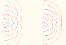
I think I'd be more lenient than that (although only measurements would tell for sure). For one thing, the cones would be almost touching. If you wanted to argue that cone width is inconsistent with height, I'd suggest the regions between where the cone is 60-100% (+/-20%) of maximum is a half wavelength at 1500Hz.Uh-huh. You can't use a 15" in a line array above ~250Hz because of the comb filter effect forming at such great distances from the middle of the driver to the next.
Below is a drawing of wavefronts with 1 wavelength spacing vs 1/2 wavelength spacing.
Attachments
24 Hz is maybe interesting for HiFi or for infras. No capable infra driver goes up to 1kHz for a reason. And I said numerous times you can't use the midrange at high excursions because your requirements are unnecessarily widespread and hard to reach. Not impossible but not reasonable (if not useless) and very expensive. You never once said you want a subwoofer driver and you never cleared up why the combination of the very high excursion and the midrange capabilities. You were talking about 'not a typical subwoofer' and mentioned the BL loss for midwoofers. You simply ignored my interjections and questions about the midrange...
You'd have saved us all a lot of time of everyone if you'd have mentioned you wanted to build a PA subwoofer driver. Why didn't you?
You're obviously missing some design objectives and considerations here.
What Snickers-is trying to accomplish has been clearly stated earlier in this thread. It's a balancing act, true, but entirely possible within the defined limits.
Several commercially available 15" midwoofers can be used up to 1000Hz without major flaws (regarding IMD etc.), but none with Fs <30Hz.
Last edited:
@Snickers-is
I hope you're doing well and this project will continue to develop.
I am doing very well Thank you @Zvu
The project is going quite a bit better than expected. I am talking about the entire audio consulting/product development project. The plan was to attack the market by realizing several drivers and hope to attract the attention of some OEMs. But before I knew it, the OEMs started reaching out, and nowdays I am really busy.
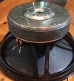
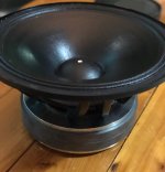
I do have a few samples of the 15 here now. Some versions have been made for OEMs already, and I have not yet found time to finish the version for the DIY market, but it is right around the corner.
As we speak, I am also developing other size drivers, including a compression driver I spoke about earlier. A suitable horn for 700-750Hz XO will also appear. A port tube system with some unusual features are due to come this year, and I believe a few 8 inch woofers and a quite unusual coaxial driver are all in the works.
The port tube system sounds interesting, I have noticed that simple ports are subject to spurious midrange output but several manufacturers have incorporated lossy elements at strategic points along their ports to effectively eliminate these issues. It may be a small market but a section of pre-made port tubes incorporating these features would be of interest to Diy'ers. Another issue with ports is that for modern high excursion drivers most off the shelf ports are too small for subs and using things like waste pipe you have to make your own flares (which are probably very sub optimal) so perhaps a selection of large port tubes and flares would sell well.
I am doing very well Thank you @Zvu
The project is going quite a bit better than expected. I am talking about the entire audio consulting/product development project. The plan was to attack the market by realizing several drivers and hope to attract the attention of some OEMs. But before I knew it, the OEMs started reaching out, and nowdays I am really busy.
I do have a few samples of the 15 here now. Some versions have been made for OEMs already, and I have not yet found time to finish the version for the DIY market, but it is right around the corner.
As we speak, I am also developing other size drivers, including a compression driver I spoke about earlier. A suitable horn for 700-750Hz XO will also appear. A port tube system with some unusual features are due to come this year, and I believe a few 8 inch woofers and a quite unusual coaxial driver are all in the works.
I am very interested in your 15


Can you please send me a PM with more specs and details, Pricing?
The port tube system sounds interesting, I have noticed that simple ports are subject to spurious midrange output but several manufacturers have incorporated lossy elements at strategic points along their ports to effectively eliminate these issues. It may be a small market but a section of pre-made port tubes incorporating these features would be of interest to Diy'ers. Another issue with ports is that for modern high excursion drivers most off the shelf ports are too small for subs and using things like waste pipe you have to make your own flares (which are probably very sub optimal) so perhaps a selection of large port tubes and flares would sell well.
Hi, I totally agree, there is a need for this.
The idea is as follows:
- The system is compatible with standard ABS plumbing tubes.
- It is a concentric port with a core element to give the entire exit a larger circumference so that it can withstand higher flow speeds.
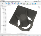
- The flare has a cross section profile that is exponential with a low coefficient so that the air speed is gradually reduced until it reaches the roundover. The cross section of the exit is therefore around 3 times the cross section of the tube itself.
- The core of the concentric tube is a closed ends quarter wave resonator that is designed to absorb the main mode of the main tube. It does this through a diffused part mid way through the tube. At this point the main tube has a pressure maximum while the inner tube has a node.
- The system allows for a slightly smaller tube, thus shorter, compared to typical ports. This raises the fundamental mode of the entire port. And since the fundamental mode is absorbed, the secondary mode, which is also raised due to the shortened port, will be around 2,5 times higher than comparable solutions.
I am planning to make documentation that describes the effective acoustic length of each part. I also plan to make laminar bends with separate ducts and larger radius to make the air less turbulent through the bend.
This is what the flare looks like at this point. It uses a 90mm + a 50mm tube, and the flare is 99x99mm with 5mm corner radius:
Attachments
I am very interested in your 15
Can you please send me a PM with more specs and details, Pricing?
Sure, but I believe you find some preliminary specs earlier in this thread as well. The retail release offer will be around 600USD/pc, depending on the exchange rate.
The flow out of the tube is different from the flow in a tube the same size without the inner tube. In a normal tube the airspeed is highest along the edge of the tube so in the turbulent region the airspeed is much greater than in the center of the tube. The core displacement tube makes another turbulent region distributing the high velocity airflow between two regions. The total high velocity edge of this tube is around 520mm while for a typical tube with the same cross section the edge is around 230mm. This means it can handle a higher mean velocity allowing for a smaller cross section of the tube. This in turn makes the tube shorter for a given tuning frequency.
Now what exactly does that link in p. 96 tell us we did not know before?
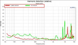
Also: 1978 is certainly not the year manufacturers steered abway form AlNiCo: that was rather 1968 or even earlier. I was hoping to learn by what techniques BL vs Excursion in woofer motors can be improved, supported by some graphs and FEMM/COMSOL sims vs measurements, but all this is general vagueness. The secrets are not revealed at all......
Sorry to have to say this, but Lars R. is thankfully much more concrete and specific. And so are the various Klippel docs.
It is about to appear on www.tonalab.com . I can make a note when it is.
- Home
- Loudspeakers
- Multi-Way
- The birth of a 15 inch woofer