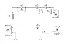
I would like to save two amplification channels for other purposes and run a SE valve amp for the MF and HF, therefore I would like to use a passive crossover between the MF and HF horn. I measured responses at 0.5 m with 4 cycle FDW in REW and also impedances. I entered everything into the XSim. I played around a lot and this is the best I could come up with (see attachments). A simple capacitor just did not work at all.
I am pretty sure I made some gross design mistakes here, so I would really appreciate any input on this. The input files are here: JBL2445-CP385Nd.zip CP385NdFR.frd, CP385NdZ.zma, JBL2445-CP385Nd.dxo, JBL2445FR.frd, JBL2445Z.zma - ShareGadget.com Share Send files by air mail - Share your files - Upload your file here
The JBL driver was measured with the same polarity as the Beyma, so it is in fact inverted. Beyma is 8 Ohm nominal, JBL 16 Ohm nominal, but they are more like 6 Ohms and 9 Ohms around the XO point (if I measured correctly).
Attachments
The crossovers are built now. Without the resistors and 100 uF capacitor and inductors are 0.2 and 0.4 mH. The first quick listening test shows they work. Contrary to expectations, the sound is actually kind of softer, most probably due to the fact that both drivers are now fed from a SE tube amp. Measurements will follow tomorrow. The XSim program was very helpful. This leaves some amp and DSP resources for experimenting with delayed ambience speakers I have just finished (heavily inspired by bwaslo).
I think I understand - I should move the XO point based on the physical distance and compensate for the physical distance by flipping the HF phase, right? Or align the drivers/horns. I cannot say the sound is worse than with a time compensated DSP XO. I will try to measure FR and Z tomorrow. Always learning new things") Next time I will do better - the plastic horns I use now will be replaced by nicer wooden ones, I will try to keep this in mind.
Next time I will do better - the plastic horns I use now will be replaced by nicer wooden ones, I will try to keep this in mind.
Next time I will do better - the plastic horns I use now will be replaced by nicer wooden ones, I will try to keep this in mind.GM, I thought at first I understand, but I am afraid I do not Was I right in my statement above? With physically aligned drivers, the FR looks good. When I add the 15 cm distance (that is the 15 in your formula, right?), it is not too good. Are there any papers/formulas on how to do this? Gapping means having different XO points for LP and HP? I have read here about the JMLC and S.Harsch crossover alignments, but I think none of these would work for such a high crossover point and 15 cm mis-alignment.
You once recommended using identical horns for the MF and HF - I have not tried that yet because the 1" to 2" adapters have not arrived yet. Then, the HF would be actually behind the MF with the horn fronts aligned. I might try to get a horn with the correct depth, which would time align the drivers. Would that solve the problem?
It is not really a problem in the sound, I think I can live with that, but it is definitely not proper engineering.
Was I right in my statement above? With physically aligned drivers, the FR looks good. When I add the 15 cm distance (that is the 15 in your formula, right?), it is not too good. Are there any papers/formulas on how to do this? Gapping means having different XO points for LP and HP? I have read here about the JMLC and S.Harsch crossover alignments, but I think none of these would work for such a high crossover point and 15 cm mis-alignment. You once recommended using identical horns for the MF and HF - I have not tried that yet because the 1" to 2" adapters have not arrived yet. Then, the HF would be actually behind the MF with the horn fronts aligned. I might try to get a horn with the correct depth, which would time align the drivers. Would that solve the problem?
It is not really a problem in the sound, I think I can live with that, but it is definitely not proper engineering.
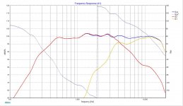
This measurement shows two things.
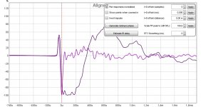
a) XSim is (unfortunately ) quite accurate for showing the dips. The surprising thing for me is, how much even a minor misalignment influences the FR. 6 inches is by no means minor, I need to do something about that.
b) Somewhere in the process I accidentally attenuated the MID FR by 5 dB - so I must add this attenuation physically. 3R3 in series and 10R in parallel with the MF driver will do it That was the true reason for the soft sound - HF driver was 5 dB lower relative to the MF driver.
a) XSim is (unfortunately
) quite accurate for showing the dips. The surprising thing for me is, how much even a minor misalignment influences the FR. 6 inches is by no means minor, I need to do something about that.b) Somewhere in the process I accidentally attenuated the MID FR by 5 dB - so I must add this attenuation physically. 3R3 in series and 10R in parallel with the MF driver will do it
That was the true reason for the soft sound - HF driver was 5 dB lower relative to the MF driver.Attachments
Last edited:
No, I will not give up! I moved the CP385Nd drivers to BC ME20 horn and made a variable position horn holder. I will align the drivers perfectly, that will be a success I hope. I know I am most probably introducing some reflections from the holder, but since the horn is used above 4 kHz, placing absorbent material in front of it should cure them.
Attachments
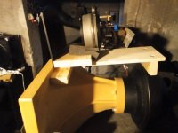
No, I will not give up! I moved the CP385Nd drivers to BC ME20 horn and made a variable position horn holder. I will align the drivers perfectly, that will be a success I hope. I know I am most probably introducing some reflections from the holder, but since the horn is used above 4 kHz, placing absorbent material in front of it should cure them.
What the horn of the JBL?
thanks
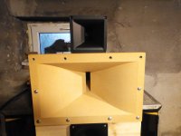
This one - ARB2" - bsacoustic.com - it is supposed to be a JBL2380 clone.
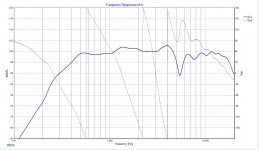
10 ohm resistor in paralled with the JBL2445 helped to balance out the sound. Also, positioning the ME20 to the correct place made things sound better. There is now a gentle slope towards HF, which is good. But for the ultimate solution of alignment problem, I will use another pair of 2380A with a 3D printed adapter: 3D printed 1" to 2" driver adapter - anyone tried before?
It will most probably need a bit more attenuation for the MF though. I hope the result to be a perfect impulse response and with a bit of DSP EQ a nice frequency and power response with good directivity.
It will most probably need a bit more attenuation for the MF though. I hope the result to be a perfect impulse response and with a bit of DSP EQ a nice frequency and power response with good directivity.
Using another 2380A for the Beyma is da thing! Even with this passive crossover, the Impulse response is almost perfect when aligned properly. If the weather permits, I will try to do some polar measurements outside, but I think now it is as good as it gets with a passive XO.
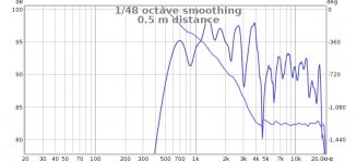
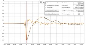
In order to know what to look for - which impulse/step response does look the best to you? It is with the crossover shown in the attachment. I also add the different FRs varying the offset and selected two best looking (psychoacoustic smoothing). This is done indoor, I need to take it out. All measured on axis, height in the middle of the two horns.
Attachments
-
 27mmOffset.jpg111.6 KB · Views: 48
 -
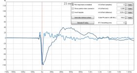 23mmOffset.jpg113 KB · Views: 41
 -
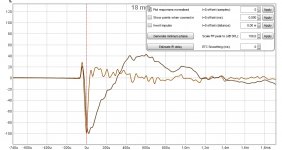 18mmOffset.jpg111.5 KB · Views: 49
 -
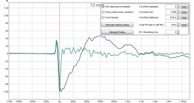 12mmOffset.jpg111.6 KB · Views: 45
 -
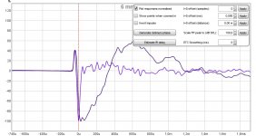 6mmOffset.jpg114.3 KB · Views: 119
 -
 0mmOffset.jpg116.6 KB · Views: 126
 -
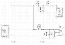 XoverSemiFinal.jpg56.7 KB · Views: 56
 -
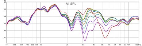 AllSPL.jpg88.6 KB · Views: 54
 -
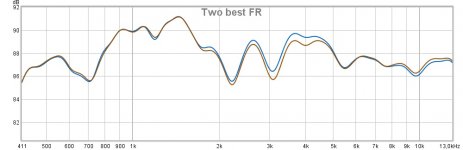 TwoBestFR.jpg59.1 KB · Views: 44
- Status
- This old topic is closed. If you want to reopen this topic, contact a moderator using the "Report Post" button.
- Home
- Loudspeakers
- Multi-Way
- JBL2445 to Beyma CP385Nd crossover tuning