I have for some time followed various threads of multiple entry horns and finally got my own project started. However, I don’t have a quality table saw that a MEH project requires, nor the extra skills and tools needed, let alone a place to put it.
Perhaps I share this inadequacy with other DIYaudio members.
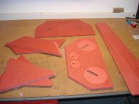
The following is my experience at designing and manufacturing Multiple Entry Horns as the Prime Mover in a Group Buy project involving a CAD/CAM process and routed by CNC to flatpacks like below:
Despite some cost doing Computer Numeric Control, we are very happy with the appearance and performance of the horns so far.
We hope the following can serve to inspire other DIYaudio members, and we shall strive to pass-on as many of the data aquired, as the project goes along, to hopefully act as a stepstone for a CNC MEH project that you may have in mind.
“Beloved child has many names” a DK saying goes, so let me start by dubbing my horn the “Rashorn” as part of my surname.
Instead of filling this thread with text and illustrations which take up space, and will take ages for me, you are welcome to my cloud at:
ME Horns by CNC - Google Drive
where I have put the final drawings and some pics., and posted this document as an evolving document, that I hope to maintain as the project goes on.
Currently, as you will see, the horn structures are ready, but the DSP cross-over is in an early stage.
Perhaps I share this inadequacy with other DIYaudio members.
The following is my experience at designing and manufacturing Multiple Entry Horns as the Prime Mover in a Group Buy project involving a CAD/CAM process and routed by CNC to flatpacks like below:
Despite some cost doing Computer Numeric Control, we are very happy with the appearance and performance of the horns so far.
We hope the following can serve to inspire other DIYaudio members, and we shall strive to pass-on as many of the data aquired, as the project goes along, to hopefully act as a stepstone for a CNC MEH project that you may have in mind.
“Beloved child has many names” a DK saying goes, so let me start by dubbing my horn the “Rashorn” as part of my surname.
Instead of filling this thread with text and illustrations which take up space, and will take ages for me, you are welcome to my cloud at:
ME Horns by CNC - Google Drive
where I have put the final drawings and some pics., and posted this document as an evolving document, that I hope to maintain as the project goes on.
Currently, as you will see, the horn structures are ready, but the DSP cross-over is in an early stage.
Attachments
we are very happy with the appearance and performance of the horns so far...
Very nice work, impressive coordination of the 3d models and CNC.
I look forward to see your DSP details.
My compliments!
Best wishes
David
Nice! VERY thorough work there (as described in your document).
I'm glad that the FR-5 midranges worked out for you. I tried that on a later plywood horn, but had some problems (probably with the horn itself, I tried to change too many things at one time and lost track of what was causing what effects).
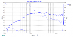
I'm surprised that the HF response seems kind of bumpy, I wonder what that might be about? Are you rounding the throat entry for the DE250? I used a 1" drill to take the square to round, when I did the Cosynes, then blended it a little more with some sandpaper. I don't know what effect that might have had. I'm using a DE250 (well, a good clone of it) now with a 3D printed horn following 'oblate spheroid' curve there and the response with that came out reasonably smooth (see attached)

I don't quite see what the narrow board that are on just forward of the woofers outside the board are for?
 Is that a mounting arrangement maybe?
I'm glad that the FR-5 midranges worked out for you. I tried that on a later plywood horn, but had some problems (probably with the horn itself, I tried to change too many things at one time and lost track of what was causing what effects).
I'm surprised that the HF response seems kind of bumpy, I wonder what that might be about? Are you rounding the throat entry for the DE250? I used a 1" drill to take the square to round, when I did the Cosynes, then blended it a little more with some sandpaper. I don't know what effect that might have had. I'm using a DE250 (well, a good clone of it) now with a 3D printed horn following 'oblate spheroid' curve there and the response with that came out reasonably smooth (see attached)
I don't quite see what the narrow board that are on just forward of the woofers outside the board are for?
Attachments
Last edited:
Thanks Bill, you know you made the inspiration ;-)
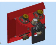
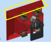
The throat section is "raw". The round-to-square section as routed. Indeed, some sanding could smooth things, but as it is, it should maintain conical expansion all the way in to only 2mm from the CD driver exit (stainless steel flange thickness).
I am not sure what you mean by "in front of the woofers", but I think you refer to the long pieces of the final flare. I did not bother to cut the corners back at some strange angle. Instead it simply continue to the plane of the edges of the short pieces of the final flare. By this, a plane face develops on the sides, which will make it easier to make some fixing of the horn to the rear chamber with less visible screws.
If you mean the white blobs in the pic., they are simply 3D printed fill-ins, made only for a nice appearence, seemingly blending three faces together.
(yes, I know its on the back, but hey guys, why do we do this ?
Because its fun !)
Impressive project, I guess from the assembly instructions and parts lists your planning on offering a kit for sale?
Looking at the individual driver frequency responses the sensitivity on the DE250 seems low? getting up to 2kHz on the mid-range is very good. I would guess maximum output of this design is limited by the woofer sections low bass capability where it no longer has horn loading?
Looking at the individual driver frequency responses the sensitivity on the DE250 seems low? getting up to 2kHz on the mid-range is very good. I would guess maximum output of this design is limited by the woofer sections low bass capability where it no longer has horn loading?
")
Better pictures
Reply to post #10, Badman
Did you look in the folders "Better pictures", also in the cloud link in post no. 1 ?
Some documents/pics suffer from being eksported as .pdf.
Therefore I put in each picture in the docs in a separate folder, in same sequence as you see them in the docs.
Reply to post #10, Badman
Did you look in the folders "Better pictures", also in the cloud link in post no. 1 ?
Some documents/pics suffer from being eksported as .pdf.
Therefore I put in each picture in the docs in a separate folder, in same sequence as you see them in the docs.
Reply to post #3, Bwaslo:
I did a comparison of the Gento's and two Visatons some time ago, as part of my studies of effects of the Helmholtz chamber between drivers and horn.
You'll see it as pic. #11 in the recent directory "Study of Vtc Atc and Lpt" in the cloud link in post #1.
There is not much difference as I see it.
The gento's are more sensitive, or the peak is smaller (which BTW is maybe less desireable since we want a "big bang" up there to push up the response)
Reply to Sarres, post #13 (Sergej)
Sorry for this late reply.
For some reason, I dont get Email notifications of my subscribed threads anymore, so I miss things.
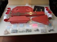
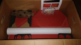
If you plan to build a set of MEH's just like mine, I can offer you a complete set (two horns) at cost price, ready for Visaton FRS 5X and B&C DE250.
Surprisingly 400+ parts, counting all bolts and inserts too.
Refer to the folder "Surplus Items" with the assembly instructions in my signature link below.
Sorry for this late reply.
For some reason, I dont get Email notifications of my subscribed threads anymore, so I miss things.
If you plan to build a set of MEH's just like mine, I can offer you a complete set (two horns) at cost price, ready for Visaton FRS 5X and B&C DE250.
Surprisingly 400+ parts, counting all bolts and inserts too.
Refer to the folder "Surplus Items" with the assembly instructions in my signature link below.
Attachments
- Status
- This old topic is closed. If you want to reopen this topic, contact a moderator using the "Report Post" button.
- Home
- Loudspeakers
- Multi-Way
- Multiple Entry Horns by CNC as flatpacks